Познакомьтесь с нами
Рекуперация отработанного тепла и химическое оборудование
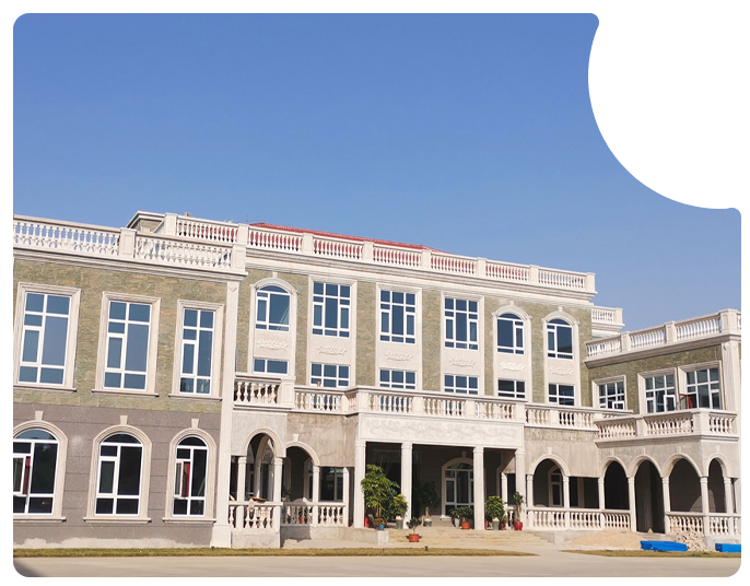
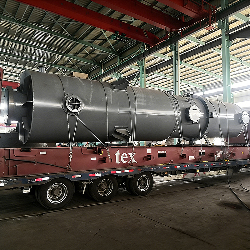
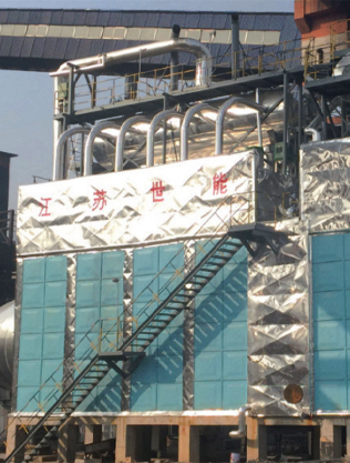
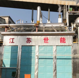
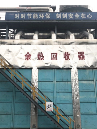
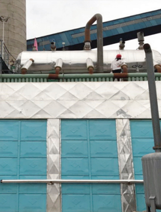
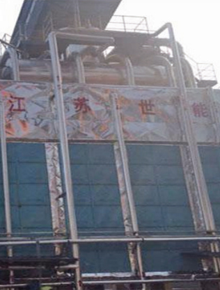
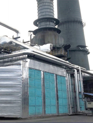
Основанная в 2005 году, компания специализируется на НИОКР и производстве систем рекуперации отходящего тепла дымовых газов и химического оборудования, обладая комплексными собственными возможностями, охватывающими разработку тепловых труб и пайку на основе никеля, а также изготовление сосудов высокого давления. Наша продукция широко используется в угольной химической, металлургической, энергетической и синтетической аммиачной промышленности и экспортируется на зарубежные рынки.
Jiangsu Shineng Chemical Equipment Co., Ltd.
Jiangsu Shineng Chemical Equipment Co., Ltd. Jiangsu Shineng Chemical Equipment Co., Ltd. Jiangsu Shineng Chemical Equipment Co., Ltd.
  • Jiangsu Shineng Chemical Equipment Co., Ltd.
    Гарантия качества

    Сертификация по стандартам ASME и сосудов высокого давления класса III, действуют комплексные системы менеджмента ISO. Современное оборудование и квалифицированный персонал обеспечивают строгий контроль качества на всех этапах производства.

  • Jiangsu Shineng Chemical Equipment Co., Ltd.
    Дизайн Инновации

    Компания располагает специализированным НИИ тепловых труб и партнерскими отношениями с высшими учебными заведениями. Имеет почти 100 патентов, в том числе технологию никелевой пайки 16-метровых оребренных труб..

  • Jiangsu Shineng Chemical Equipment Co., Ltd.
    Влияние отрасли

    Компания является уполномоченным поставщиком по разработке национальных стандартов химического машиностроения. Продукция поставляется для ключевых отраслей Китая и зарубежья, получив широкое рыночное признание.

Широкий спектр отраслей
Отрасли нашего обслуживания
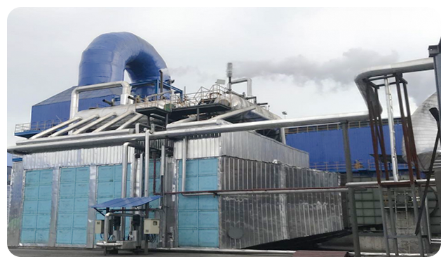
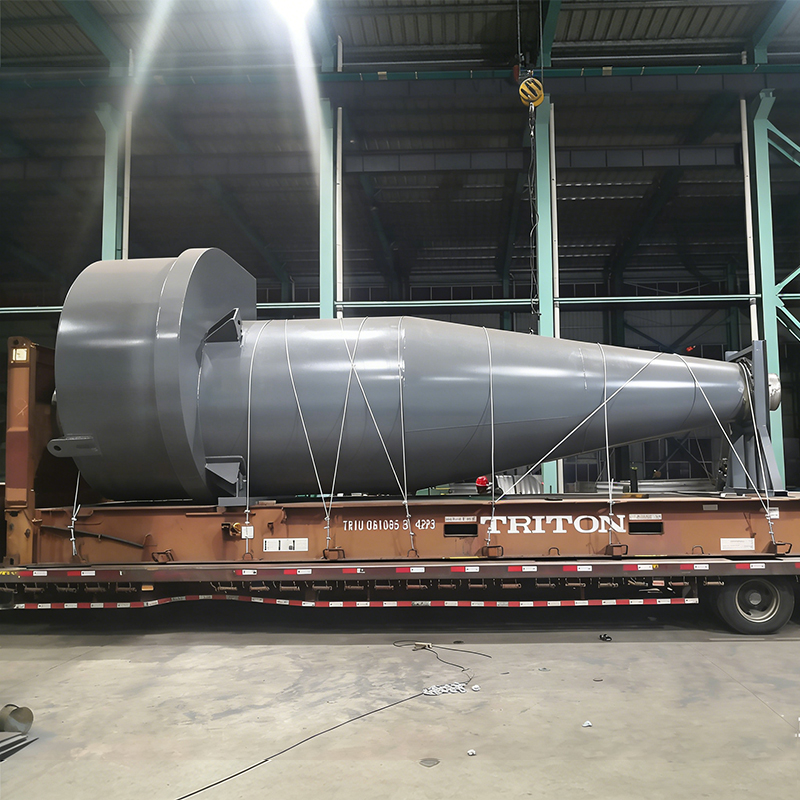
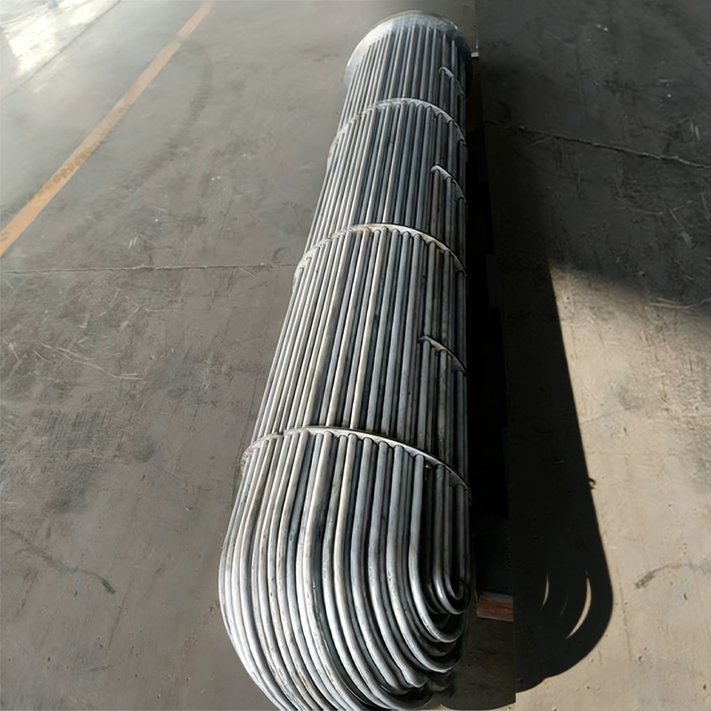
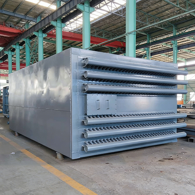
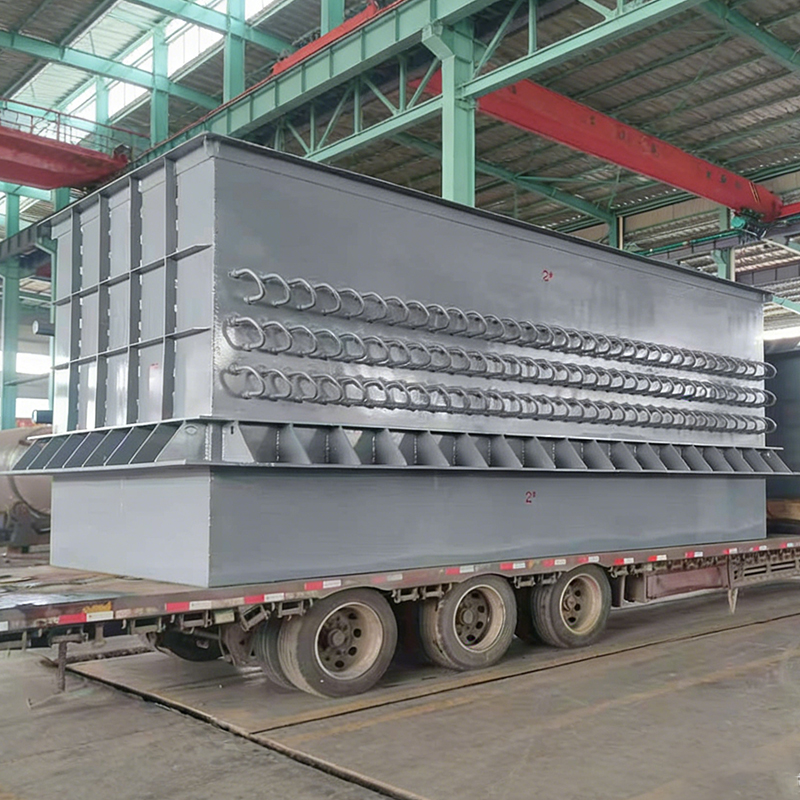
Мы поставляем основное технологическое оборудование: экономайзеры на тепловых трубах, котлы-утилизаторы, подогреватели воздуха, циклонные пылеуловители, теплообменное оборудование и градирни для отраслей углехимии, энергетики, металлургии и производства синтетического аммиака. Компания выполняет комплексное проектирование, изготовление и ввод в эксплуатацию системных проектов рекуперации отходящего тепла.
  • Jiangsu Shineng Chemical Equipment Co., Ltd.
  • Jiangsu Shineng Chemical Equipment Co., Ltd.
  • Jiangsu Shineng Chemical Equipment Co., Ltd.
  • Jiangsu Shineng Chemical Equipment Co., Ltd.
Jiangsu Shineng Chemical Equipment Co., Ltd.
Категории продуктов
Наши популярные продукты

Jiangsu Shineng Chemical Equipment Co., Ltd. — известный профессиональный производитель высокоэффективного теплообменного оборудования на тепловых трубах, комплектного оборудования котлов-утилизаторов и оборудования для сосудов высокого давления в Китае.

Jiangsu Shineng Chemical Equipment Co., Ltd.
Новости и блоги
Другие отраслевые новости

Мы постоянно публикуем актуальные сведения о компании и отрасли. Свяжитесь с нами и следите за информацией о наших выставочных мероприятиях.

Jiangsu Shineng Chemical Equipment Co., Ltd.
  • Jiangsu Shineng Chemical Equipment Co., Ltd.

    Продувка котла — это контролируемое удаление концентрированной котловой воды из парового барабана или нижних коллекторов для поддержания взвешенных и растворенных твердых веществ в безопасных пределах. Это не признак плохой работы; это необходимая часть управления водно-химическим режимом промышленных котлов. Эффективный план продувки защищает поверхности теплопередачи, улучшает качество пара и снижает затраты на техническое обслуживание. Для заводских инженеров и групп по закупкам задача состоит в том, чтобы сбалансировать контроль водно-химического режима с энергоэффективностью. В этом руководстве объясняются основы продувки котла, процедуры безопасной эксплуатации, варианты рекуперации тепла, а также критерии выбора надежного оборудования и поставщиков.

    Что такое продувка в котле?

    Продувка – это преднамеренный сброс части котловой воды и замена ее питательной водой с меньшим содержанием растворенных веществ. Питательная вода каждого котла содержит примеси, такие как кальций, магний, кремнезем, хлориды и щелочность. Когда питательная вода превращается в пар, эти примеси остаются и накапливаются в котловой воде. По мере увеличения общего содержания растворенных твердых веществ (TDS) вода становится более проводящей, имеет тенденцию к пенообразованию и может выделять с паром капли, содержащие растворенные твердые вещества. Эта проблема известна как перенос. Накипь начинает откладываться на поверхности трубок и барабанов, когда кальций и магний превышают пределы растворимости. Таким образом, цель продувки котла состоит в том, чтобы поддерживать TDS и взвешенные твердые частицы ниже порога, при котором могут произойти образование накипи, коррозия или перенос. Продувка может быть ручной или автоматической, периодической или непрерывной, в зависимости от типа котла и стратегии водоподготовки.

    Продувка — это водно-химический инструмент, а не поток отходов, который следует игнорировать: правильная скорость обеспечивает чистоту котла без сжигания избыточного топлива.

    Почему продувка имеет значение: эффективность, безопасность и химический состав воды

    Образование накипи на трубах котла является наиболее частым последствием недостаточной продувки. Даже тонкий слой окалины действует как изолятор, замедляя теплообмен и вызывая повышение температуры металла трубы. Со временем это приводит к перегреву, выходу из строя трубок и дорогостоящему ремонту. Перенос оказывает столь же серьезное влияние на качество пара. Пар, содержащий котловую воду, содержит растворенные соли, которые могут откладываться на лопатках турбин, поверхностях теплообменников и технологического оборудования. Коррозия, часто накипная, еще больше ослабляет детали, находящиеся под давлением. Сама по себе продувка может показаться небольшой потерей воды, но с точки зрения энергии каждый слив выбрасывает насыщенную воду из котла. Задача состоит в том, чтобы удалить достаточное количество твердых частиц, чтобы сохранить котел в чистоте, не теряя при этом чрезмерного тепла. Поэтому операторы установок должны измерять TDS или проводимость с определенной частотой и устанавливать целевой диапазон на основе давления в котле и рекомендаций производителя.

    Скорость продувки напрямую влияет на общую эффективность котла, поскольку горячая вода, выходящая из котла, должна восполняться за счет нагрева холодной питательной воды. На многих промышленных предприятиях скорость продувки не измеряется, поэтому потери энергии скрываются за рутинной работой. Визуальное сравнение помогает командам предприятий понять масштабы этих потерь при обычных скоростях продувки. Горизонтальные полосы ниже показывают типичные потери энергии топлива при скорости продувки 1%, 2%, 5% и 10% при рабочем давлении от 10 до 15 бар. Значения являются приблизительными и зависят от температуры питательной воды, давления в котле и оборудования рекуперации тепла.

    1% ДР
    0,5%
    2% ДР
    1,0%
    5% ДР
    2,5%
    10% ДР
    5,0%

    Диаграмма показывает, что уровень продувки в 1% приводит к относительно небольшому расходу топлива, хотя, возможно, его все же стоит компенсировать. При 2% завод начинает ощущать затраты на топливо, если котел работает непрерывно. При 5% потери энергии становятся основными эксплуатационными расходами, особенно для котлов производительностью более 10 т/ч. При 10% потери топлива могут составлять от 3 до 5% и выше, что часто свидетельствует о плохой очистке питательной воды или неправильном управлении. Например, снижение степени продувки с 10% до 2% может повысить эффективность котла примерно на 3%. Для котла производительностью 20 т/ч, работающего 8000 часов в год, это может сэкономить сотни мегаватт-часов эквивалента топлива. Лучший подход — регулярно брать пробы котловой воды и регулировать продувку для поддержания целевого TDS. Многие операторы используют простое правило: продувайте ровно столько, сколько необходимо, чтобы поддерживать TDS ниже предела, установленного для давления в котле. Рекуперация тепла может снизить стоимость неизбежной продувки. Если непрерывный поток продувки направляется через теплообменник, большая часть энтальпии может быть возвращена в систему. Именно поэтому современные предприятия относятся к продувкам не как к отходам, а как к восстанавливаемому ресурсу.

    Оптимальная скорость продувки — это минимальная скорость, которая удерживает химический состав котловой воды в безопасных пределах.

    Виды продувки котла

    Продувку котла обычно разделяют на два основных метода: нижнюю продувку и поверхностную продувку. Они нацелены на разные типы загрязнений и действуют по разным графикам. Нижняя продувка удаляет шлам и осадок, которые оседают в самых нижних частях котла. Поверхностная продувка удаляет растворенные твердые частицы и пену, которые концентрируются вблизи ватерлинии. В таблице ниже приведены основные различия.

    Сравнение нижней и поверхностной продувки.
    Параметр Нижняя продувка Поверхностная продувка
    Основная цель Шлам, осадок, взвешенные вещества Растворенные твердые вещества, пена, накипь
    Расположение Нижняя часть грязевого барабана и коллекторов Около ватерлинии в паровом барабане
    Метод работы Прерывистые, короткие всплески Непрерывный или прерывистый скиммер
    Выпускной клапан Высокий поток, низкая продолжительность Низкий поток, большая продолжительность
    Пригодность к рекуперации тепла Менее подходит из-за прерывистого потока. Очень подходит для непрерывной рекуперации тепла.

    Непрерывная и прерывистая продувка

    Продувка поверхности часто осуществляется непрерывно для поддержания стабильного уровня TDS. Небольшая струя воды отбирается из парового барабана и заменяется питательной водой. Автоматические контроллеры измеряют проводимость и модулируют работу клапана для достижения целевого заданного значения. Прерывистая продувка, напротив, представляет собой периодическую ручную операцию. Он более эффективен для удаления осадка из самых нижних частей котла. Непрерывная продувка обычно предпочтительна для контроля растворенных твердых веществ, в то время как периодическая продувка днища остается необходимой для удаления отложений.

    Используйте непрерывную продувку поверхности для контроля концентрации химикатов и периодическую продувку днища для удаления осадка.

    Компоненты системы продувки и порядок безопасной эксплуатации

    Хорошо спроектированная линия продувки обычно включает в себя клапан медленного открытия, клапан быстрого открытия, тройник и резервуар для продувки или охлаждающий резервуар. Клапан медленного открытия обычно устанавливается ближе всего к котлу и используется для дросселирования потока в первый раз. Быстрооткрывающийся клапан расположен ниже по потоку и действует как регулятор включения/выключения. Для контроля качества воды добавляются охладители отбора проб и датчики проводимости. В автоматических системах ручной быстрооткрывающийся клапан заменяется модулирующим клапаном с электроприводом или пневмоприводом.

    • Клапан медленного открытия: защищает внешний клапан от сильной эрозии.
    • Быстрооткрывающийся или шаровой клапан: обеспечивает быструю изоляцию включения/выключения.
    • Продувочный резервуар или испарительный резервуар: охлаждает выпуск и отделяет выпарной пар.
    • Охладитель проб: безопасно снижает температуру для точного измерения TDS.
    • Датчик проводимости и контроллер: обеспечивают непрерывную автоматическую продувку.

    Безопасная ручная продувка осуществляется в строгой последовательности. Точная последовательность может варьироваться в зависимости от расположения клапана, но основной принцип заключается в том, чтобы избегать создания давления или нагрева закрытого участка трубы.

    1. Убедитесь, что давление в котле находится в пределах нормы и продувочный резервуар готов.
    2. Сообщите об этом эксплуатационному персоналу и изолируйте все расположенное ниже оборудование, которое может быть повреждено.
    3. Сначала откройте медленно открывающийся клапан, ближайший к давлению котла.
    4. Медленно откройте быстрооткрывающийся клапан на короткий период слива.
    5. Закройте быстрооткрывающийся клапан, дайте котлу стабилизироваться и повторите при необходимости.
    6. После последнего хода сначала закройте быстрооткрывающийся клапан, затем медленно открывающийся клапан.
    7. Проверьте выходной трубопровод на наличие утечек или признаков перегрева опор.

    Операторы должны стоять в стороне от линии нагнетания и носить полный комплект средств индивидуальной защиты. Горячая вода и пар выбрасываются с большой скоростью и могут вызвать серьезные ожоги. Никогда не оставляйте продувающийся котел без присмотра. Если труба вибрирует или клапаны протекают, прекратите работу и осмотрите систему, прежде чем продолжить. На объектах, где требуется дистанционное или автоматическое управление, такие же защитные блокировки следует применять к клапанам с электроприводом.

    Всегда изолируйте напорную сторону котла перед удалением воздуха и никогда не предполагайте, что клапан герметичен без проверки дренажной линии.

    Утилизация тепла при продувке котла

    Потоки продувки покидают котел при температуре насыщения. В котле с давлением 10 бар это около 180°C; в котле на 40 бар она может быть выше 250°C. Слив этой горячей воды непосредственно в дренаж приводит к потере большого количества тепловой энергии. В расширительном баке сначала снижается давление, и часть горячей воды преобразуется в пар низкого давления, который можно использовать в деаэраторе или для отопления помещений. Оставшаяся горячая жидкость все еще содержит тепло. Теплообменник может передавать это остаточное тепло подпиточной воде, питательной воде котла или технической воде. Эта простая модернизация часто окупается менее чем за два года, особенно в системах непрерывной продувки.

    Кожухотрубный теплообменник является распространенным выбором для продувочного охлаждения и рекуперации тепла, поскольку он может выдерживать высокое давление, высокую температуру и термический удар. Это также дает предприятию возможность использовать рекуперированное тепло в различных целях.

    Shell and Tube Heat Exchanger for High-Pressure Blowdown Cooling Кожухотрубный теплообменник для продувочного охлаждения под высоким давлением Этот прочный теплообменник выдерживает высокое давление, температуру и термический шок, что делает его идеальным для продувочного охлаждения и рекуперации тепла. Его гибкая конструкция подходит для различных служб предприятия. Посмотреть продукт →

    Технология паяного экономайзера на основе никеля — еще один проверенный способ улавливания тепла из потоков горячей воды или дымовых газов, где стойкость к коррозии имеет решающее значение. Этот тип экономайзера предназначен для сложных промышленных условий и может быть интегрирован с предварительным подогревом питательной воды.

    Nickel-based Brazed Economizer for Corrosive Flue Gas Heat Recovery Паяный экономайзер на основе никеля для рекуперации тепла коррозионных дымовых газов Этот экономайзер, разработанный для сложных промышленных условий, обеспечивает высокую коррозионную стойкость и высокую эффективность теплопередачи, помогая рекуперировать тепло из потоков горячей воды или дымовых газов. Посмотреть продукт →

    Для предприятий, предпочитающих комплексное решение, блоки испарителя и теплообменника могут сочетать мгновенное охлаждение, нагрев жидкости и очистку конденсата в одном инженерном блоке. Такие системы полезны, когда котельной требуется полный контур рекуперации, а не один компонент.

    Integrated Evaporator and Heat Exchanger Package for Complete Recovery Loops Интегрированный комплект испарителя и теплообменника для контуров полной рекуперации Эта комплексная система сочетает в себе мгновенное охлаждение, нагрев жидкости и очистку конденсата в одном инженерном блоке, что полезно для котельных, требующих полного контура рекуперации, а не отдельных компонентов. Посмотреть продукт →

    При планировании проекта рекуперации тепла при продувке учитывайте часы работы, скорость потока при продувке и количество пара низкого давления, которое можно потреблять на месте. Утилизированное тепло может использоваться для предварительного нагрева подпиточной воды, повышения температуры деаэратора или подачи низкотемпературного контура горячей воды. Во многих отраслях эта рекуперация тепла сочетается с рекуперацией тепла дымовых газов самого котла, чтобы максимизировать общую эффективность установки.

    Часто можно восстановить от 50 до 80 процентов тепла в непрерывном потоке продувки, используя расширительный бак и теплообменник.

    Автоматическое управление продувкой и лучшие практики

    Ручная донная продувка по-прежнему широко распространена для удаления осадка, но непрерывный контроль TDS более точен. Датчики проводимости контролируют качество котловой воды и посылают сигналы на модулирующий регулирующий клапан. Клапан открывается ровно настолько, чтобы поддерживать желаемую уставку. Это снижает потери воды по сравнению с отбором проб вручную, предотвращает унос и стабилизирует качество пара. Контроллер можно подключить к системе SCADA предприятия для регистрации тенденций и управления сигналами тревоги.

    • Для больших котлов отбирайте пробы питательной и котловой воды не реже одного раза в смену.
    • Калибруйте датчики проводимости ежемесячно для обеспечения точности.
    • По возможности отслеживайте объем продувки с помощью расходомера.
    • Просматривайте отчеты по очистке воды и корректируйте заданное значение при изменении качества нагрузки или питательной воды.
    • Обучите операторов правильной последовательности ручных продувочных клапанов и технике безопасности.
    • Записать время нижней продувки; чрезмерная продолжительность может указывать на треснувший клапан или плохую технику.

    Хорошо контролируемая программа продувки также снижает расход химикатов. Когда TDS остается в узком диапазоне, дозирование может быть оптимизировано, а уровни ингибитора отложений становятся более предсказуемыми. Это особенно важно для современных котлов высокого давления, где даже небольшие изменения водно-химического режима могут повлиять на надежность котла.

    Автоматическое управление продувкой в ​​сочетании с регулярной нижней продувкой обеспечивает наилучший баланс между качеством пара, потребностью в воде и энергоэффективностью.

    Выбор продувочного оборудования и квалифицированного поставщика

    При модернизации котельной систему продувки следует выбирать с той же тщательностью, что и горелку или паровые барабаны. Поставщик должен понимать химический состав котловой воды, конструкцию резервуара под давлением и выбор материалов. Для компонентов, работающих под давлением, важными требованиями являются сертификация ASME и отечественная лицензия на сосуд под давлением. Производитель, имеющий опыт создания теплообменников, экономайзеров и котлов-утилизаторов, может интегрировать рекуперацию тепла продувки в общую тепловую систему установки. Примеры такого опыта утилизации тепла промышленных отходов можно увидеть в котлах-утилизаторах в металлургии, где аналогичные принципы рекуперации тепла применяются к различным потокам дымовых газов и горячей воды.

    Прежде чем выбирать поставщика, запросите тематические исследования, сертификаты материалов и графики поставок. Убедитесь, что продувочный резервуар или теплообменник изготовлен в соответствии с применимыми нормами и что система управления может взаимодействовать с существующей платформой ПЛК, РСУ или SCADA. Поставщик, который может предоставить послепродажную поддержку, запасные клапаны и сменные сердечники теплопередачи, снижает риск простоя. Покупателям крупных проектов и OEM-покупателям следует также подумать, может ли поставщик поставить полный пакет рекуперации тепла, а не один кожухотрубный теплообменник. Для OEM-покупателей и оптовиков также важно подтвердить взаимозаменяемость с существующими клапанами, фланцами и сигналами управления.

    Оцените систему управления качеством и возможности контроля производителя. Сертифицированные сварщики, гидростатические испытания и документированное отслеживание материалов являются признаками надежного поставщика. Лучшие поставщики также могут дать рекомендации по настройкам управления продувкой на основе фактического анализа питательной воды, что позволяет избежать метода проб и ошибок, распространенного на старых установках.

    Лучший поставщик сочетает в себе сертифицированную конструкцию резервуара под давлением, технологию рекуперации тепла и возможность поставить комплексную систему продувки, соответствующую нормам.

    Часто задаваемые вопросы: продувка котла

    Что такое продувка в котле?

    Продувка котла – это регулируемое удаление котловой воды для сохранения растворенных твердых веществ.

    и осадка в безопасных пределах. Предотвращает образование накипи, перенос и коррозию во время

    сохранение чистоты пара. Продувка может быть ручной или автоматической,

    прерывистый или непрерывный.

    В чем разница между нижней продувкой и поверхностной продувкой?

    Нижняя продувка удаляет шлам и осадок из нижних коллекторов и грязевого барабана.

    Поверхностная продувка удаляет растворенные твердые частицы и пену вблизи ватерлинии.

    Поверхностная продувка может быть непрерывной, тогда как нижняя продувка обычно носит прерывистый характер.

    Как часто следует продувать котел?

    Частота зависит от качества воды, нагрузки котла, давления и программы очистки.

    На многих предприятиях донную продувку проводят один раз в смену. Непрерывная поверхностная продувка

    может работать постоянно с автоматическим контролем проводимости.

    Можно ли экономично утилизировать тепло продувки?

    Да. Расширительный резервуар и теплообменник могут рекуперировать от 50 до 80 процентов тепла из

    непрерывный поток продувки. Сроки окупаемости зачастую составляют менее двух лет.

    промышленные объекты с большой продолжительностью рабочего времени.

    Какие проверки безопасности необходимы при продувке котла?

    Проверьте уровень продувочного резервуара, убедитесь, что сливные трубы не засорены,

    перед работой проверьте последовательность работы клапана, наденьте полный комплект СИЗ,

    и никогда не оставляйте систему без присмотра во время продувки.

    Если клапан протекает или труба вибрирует, немедленно прекратите работу.

    Регулярная продувка, выполняемая безопасно и автоматически, защищает внутренние детали котла и превращает необходимые потери в управляемые операционные расходы.

    Продувка котла — это рутинная процедура, имеющая серьезные последствия для безопасности, водно-химического режима и экономии топлива. Если все сделано правильно, он защищает котел, поддерживает чистоту пара и снижает затраты на коррозию и накипь. В сочетании с рекуперацией тепла это превращает необходимые потери в управляемые эксплуатационные расходы. Инженеры завода и проектные группы должны выбирать оборудование для продувки и поставщиков на основе сертифицированного опыта работы с сосудами под давлением, опыта рекуперации тепла и сервисной поддержки на протяжении всего жизненного цикла. Это практическая формула надежной и эффективной котельной системы.

    -- Sep 09, 2026
  • Jiangsu Shineng Chemical Equipment Co., Ltd.

    Могут ли котлы взорваться? Да, они могут. Но в контексте промышленного предприятия реальный вопрос заключается не только в том, возможно ли это, а в том, делают ли это возможным конструкция, материалы и рабочие процедуры на вашем предприятии. Когда руководитель завода, инженер-технолог или специалист по закупкам ищет эту фразу, они обычно сталкиваются с одним из двух сценариев: аудит безопасности, выявивший пробелы, или решение по спецификации нового котла-утилизатора. В любом случае ответ должен быть точным, а не заученным наизусть. Взрывы котлов — это не случайные физические явления. Они являются конечной точкой цепочки предсказуемых отказов: давление превышает расчетный диапазон, поверхность теплопередачи теряет свою охлаждающую способность, коррозия утончает границу давления или топливный газ находит источник возгорания. Каждый из этих отказов можно предотвратить с помощью проектных расчетов, контроля качества изготовления и строгого режима проверок.

    В данной статье вопрос рассматривается с точки зрения производителя промышленных котлов-утилизаторов, экономайзеров и теплообменников. Эта точка зрения имеет значение, поскольку профиль риска взрыва котла-утилизатора отличается от профиля риска взрыва котла-утилизатора. Котел-утилизатор часто подвергается воздействию как высокотемпературных дымовых газов со стороны корпуса, так и пароводяной системы со стороны труб. Граница между этими двумя системами — это то место, где начинается большинство инцидентов. Цель здесь — дать вам полезное и практическое понимание механизмов сбоев, стандартов, которые их регулируют, и процедур обслуживания, которые не позволяют им стать реальными событиями.

    Взрывы котлов можно предотвратить. Они возникают при одновременном нарушении систем защиты и ограничений материалов: избыточного давления, потери водяного охлаждения, утечек топлива или коррозионного повреждения.

    Что заставляет котел взрываться? Два физических механизма

    Чтобы ответить на вопрос «могут ли котлы взрываться» полезным способом, вам нужно разделить два различных физических механизма. Первый — это нарушение границы давления, часто называемое физическим взрывом. Второй — это горение или взрыв топливного газа, также называемый химическим взрывом. У них один и тот же результат — катастрофическое высвобождение энергии, — но они возникают из-за разных условий процесса и требуют разных превентивных мер.

    Физический взрыв: избыточное давление и потери охлаждения

    Физический взрыв котла происходит, когда внутреннее давление пароводяной системы превышает прочность сосуда высокого давления. В нормально работающем котле давление удерживается, поскольку вода и пар находятся в термодинамическом равновесии при контролируемой заданной температуре. Металл сосуда рассчитан на то, чтобы выдерживать это давление при соответствующей температуре насыщения. Если давление превысит расчетный предел или если температура стенки поднимется намного выше расчетной температуры, в то время как давление остается в ее пределах, металл теряет прочность и разрушается. Быстрое расширение накопленной воды и пара может высвободить энергию, эквивалентную большому заряду взрывчатого вещества.

    Наиболее распространенная последовательность физических взрывов начинается с низкого уровня воды в сочетании с продолжительным стрельбой. Когда уровень воды падает ниже труб, тепло от горелки или дымовых газов больше не может поглощаться водой. Вместо этого металл трубы быстро нагревается и теряет прочность на разрыв. Если пламя не погасить, трубка может выйти из строя, и большой объем высокотемпературной воды превратится в пар. В котле-утилизаторе та же последовательность может произойти, если массовый расход на стороне газа продолжается, а насос на стороне воды отключается. Хитрость не в том, чтобы предположить, что горелка всегда контролирует подачу тепла — в котле-утилизаторе источником тепла является предшествующий процесс, а не горелка.

    Химический взрыв: смесь топливного газа и воспламенение

    Второй механизм – химический взрыв. Это происходит, когда топливный газ — природный газ, коксовый газ или любой горючий пар — просачивается в замкнутое пространство, смешивается с воздухом, достигая предела воспламеняемости, а затем встречается с источником возгорания. В котле это может произойти в камере сгорания, дымоходе или на открытом воздухе рядом с негерметичным фланцем. Наиболее опасным состоянием является неисправность предварительной продувки: система управления горелкой позволяет топливу течь до того, как камера сгорания будет достаточно продута воздухом.

    В редких случаях возможны химические взрывы и на водной стороне. Если некоторые химические чистящие средства или продукты разложения выделяют водород и этот водород задерживается в замкнутом объеме вместе с кислородом, он может воспламениться. Однако на практике взрыв на стороне газа гораздо чаще встречается при авариях на промышленных котлах.

    Физические взрывы происходят из-за избыточного давления и перегрева труб; химические взрывы происходят в результате смешивания топливного газа с воздухом в замкнутом объеме. Профилактическая направленность различается: химический состав воды и контроль уровня на случай физических взрывов; логика продувки, проверка герметичности и обнаружение газа при химических взрывах.

    Основные причины взрывов промышленных котлов

    Статистические данные о взрывах котлов из различных справочных источников, страховых компаний и аудитов предприятий не полностью согласованы, но они сходятся в ограниченном наборе основных причин. Стоит четко заявить, что приведенные ниже пропорции представляют собой концептуальный синтез типичных видов промышленных отказов, а не точную статистическую запись какой-либо отдельной базы данных. Что имеет значение, так это ранжирование и инженерная интерпретация.

    Относительный вклад распространенных причин взрывов котлов

    Сбой защиты от избыточного давления
    32%
    Загрязнение со стороны воды и перегрев трубок
    26%
    Утечка топливного газа и воспламенение
    18%
    Коррозия, усталость и растрескивание
    15%
    Производственные дефекты и дефекты материалов
    9%

    Отказ защиты от избыточного давления является самой большой причиной. Это означает, что предохранительный клапан или предохранительное устройство не открылись тогда, когда это должно было произойти, или отсечка при низком уровне воды и блокировка пламени не отключили источник тепла. Причиной может быть заблокированный кран давления, слишком высокая установка предохранительного клапана, оставленный открытым ручной байпас или умышленно отключенная блокировка. В системах рекуперации отходящего тепла не менее опасной ситуацией является перепускная заслонка, которая остается частично открытой, позволяя горячему газу продолжать поступать в котел при отсутствии потока воды.

    Загрязнение со стороны воды занимает второе место. Это особенно актуально для экономайзеров и котлов-утилизаторов, работающих в условиях высокой запыленности дымовых газов. Отложения накипи на стороне воды действуют как изолирующий слой, предотвращая передачу тепла от металла к воде. Температура металла повышается, а в крайних случаях трубка раздувается и лопается. В стандартном котле слой накипи карбоната кальция толщиной 1 мм может повысить температуру стенки трубы на несколько сотен градусов. В котле-утилизаторе то же самое может произойти, если химический состав питательной воды плохо контролируется.

    Утечка топливного газа относится к третьей категории. На коксохимических, химических и металлургических заводах топливным газом часто является коксовый или доменный газ. Это не природный газ; они имеют разную плотность и состав, а некоторые имеют высокое содержание водорода, что делает их более склонными к обратным воспоминаниям. При неправильной продувке газовой рампы или утечке регулирующего клапана за пределы седла может образоваться взрывоопасная смесь. Обнаружение газа и правильно спроектированная последовательность предварительной продувки являются основными средствами защиты.

    Коррозия и усталость являются «медленными» причинами. Эти механизмы не приводят к внезапному сбою в первый же день. Вместо этого они уменьшают толщину границы давления или вызывают трещины, которые распространяются с годами. Котел-утилизатор, работающий с дымовым газом, температура которого ниже точки росы серной кислоты, может подвергаться серьезной низкотемпературной коррозии со стороны газа. Кислота конденсируется на поверхности трубки, и металл подвергается химической эрозии. В местах соединений трубы с коллектором может развиться коррозионное растрескивание под напряжением, особенно если не поддерживается химический состав воды и повышен уровень хлоридов.

    Оставшаяся категория — производственные дефекты — самая маленькая, но и наиболее предотвратимая. Дефектные сварные швы, плохая термообработка или неправильно указанные марки материалов могут привести к преждевременному выходу из строя. Именно поэтому такие нормы, как ASME Раздел I и Раздел VIII, а также отечественное лицензирование сосудов под давлением требуют документированных процедур сварки, квалифицированных сварщиков и неразрушающего контроля критических соединений. Когда вы покупаете у производителя, имеющего соответствующие сертификаты, этот фактор риска в значительной степени контролируется у источника.

    На долю трех причин приходится более трех четвертей риска взрыва промышленных котлов: неадекватная защита от избыточного давления, загрязнение со стороны воды, приводящее к перегреву, и утечка горючего газа. К каждому из них можно напрямую обратиться с помощью стандартов проектирования и регулярной проверки.

    Распространенные типы котлов и их профили рисков

    Не все котлы одинаково уязвимы, и на вопрос «могут ли котлы взорваться» есть разный ответ в зависимости от архитектуры котла. Жаротрубные котлы, водотрубные котлы и котлы-утилизаторы имеют разные режимы отказа. Для завода, рассматривающего возможность установки нового агрегата, понимание этого различия имеет важное значение для обоснованной спецификации.

    Сравнение типов котлов по основным характеристикам взрывоопасности
    Тип котла Объем воды Источник тепла Первичный риск взрыва Типичное применение
    Жаротрубный котел Большой Горелка/печь Накопление топливного газа, низкий уровень воды Технологический пар для небольших предприятий
    Водотрубный котел Меньший Горелка/печь Выход из строя трубки из-за накипи, избыточного давления Энергетика и крупные перерабатывающие отрасли
    Котел-утилизатор Меньший Восходящий дымовой газ Потеря потока воды при байпасе, коррозия, утечка со стороны газа. Угольная химия, металлургия, энергетика
    Электрический котел Средний Электрические нагревательные элементы Избыточное давление из-за расширения, отсутствие источника топливного газа Чистый и вспомогательный пар

    Жаротрубные котлы по своей природе компактны и имеют большой объем пара, что классически породило идею о том, что отказ котла эквивалентен «бомбе». Большой объем воды означает, что внезапный разрыв высвобождает огромное количество накопленной энергии. Риск снижается за счет поддержания тщательно контролируемого уровня воды и предотвращения скопления топлива. В жаротрубном котле пламя находится внутри трубы, поэтому вода поглощает тепло с внешней поверхности. Если уровень воды слишком низкий, венец печи обнажается и может очень быстро выйти из строя.

    Водотрубные котлы используют воду внутри труб, а дымовые газы — снаружи. Объем воды в сосуде намного меньше, обычно его достаточно, чтобы отделить пар от воды. Риск взрыва в большей степени связан с взрывом трубки, хотя локализованный взрыв все же может спровоцировать второе, более серьезное событие. В водотрубных котлах крайне важно следить за соотношением расхода воды и тепловложения. Критической точкой отказа является не весь сосуд, а режим циркуляции. Если циркуляция нарушена, трубы перегреваются, и граница давления выходит из строя.

    Котлы-утилизаторы имеют свой особый профиль риска. Обычно у них нет горелки, поэтому, строго говоря, взрыв на стороне газа топливно-воздушной смеси горелки не является типичным событием. Однако на многих предприятиях котел-утилизатор соединен с шахтой сгорания или фритюрницей, и несгоревший газ из предшествующего процесса может поступать в котел. В ваграночных или сталеплавильных дымоходных системах CO может присутствовать в отходящих газах. Утечка или перезапуск без надлежащей продувки могут привести к накоплению CO. Наиболее распространенной аварией котла-утилизатора по-прежнему является утечка труб, вызванная термическим ударом, эрозией или коррозией. Поскольку эти котлы часто располагаются в высокотемпературных и запыленных потоках дымовых газов, состояние материалов необходимо оценивать через частые промежутки времени.

    Установки рекуперации отходящего тепла также включают в себя экономайзеры, воздухоподогреватели и другое теплообменное оборудование. Например, экономайзер рекуперирует тепло дымовых газов для предварительного нагрева питательной воды котла. Поскольку температура воды ниже температуры насыщения, стенки труб подвергаются более широкому температурному диапазону, что может привести к термической усталости. Паяный экономайзер на основе никеля специально разработан для того, чтобы выдерживать коррозионные и термоциклические условия. Конструкция паяных соединений также уменьшает количество сварных соединений, которые часто являются местом отказа традиционного экономайзера.

    Coke Oven Flue Gas Waste Heat Boiler for Medium-Low Temperature Recovery Котел-утилизатор дымовых газов коксовой печи для средне-низкотемпературной рекуперации Этот котел рекуперирует отходящее тепло дымовых газов коксовой печи с температурой 260–300°C, снижая его температуру до 140–160°C при выработке пара. Секции экономайзера и испарителя с H-оребренными трубами достигают эффективности более 85 %, что делает его ключевым решением для коксохимических заводов, стремящихся к экономии энергии и сокращению выбросов. Просмотреть продукт →

    Если вы рассматриваете котел-утилизатор для дымовых газов коксовой печи или систему кольцевого охладителя спекания, наиболее важным вопросом выбора является соответствие конструкции котла фактическому составу дымовых газов и температурному профилю. Слишком маленький котел будет работать с чрезмерной скоростью дымовых газов и вызывать эрозию; котел слишком большого размера будет работать при слишком низкой температуре газа и способствовать образованию конденсата. Именно поэтому квалифицированный производитель должен принести конструкторский расчет на основе конкретного проекта, а не инженерного изделия общего назначения.

    Профиль риска взрыва котла определяется его архитектурой. Котлы-утилизаторы несут меньший риск, связанный с топливным газом, чем котлы с топкой, но они несут более высокий риск коррозии и термического удара, поскольку источником тепла является внешний процесс, который сам котел не может отключить.

    Как нормы и качество производства снижают риск

    Вопрос «могут ли котлы взорваться» обычно задается в контексте, когда уже действуют нормы и стандарты. Именно соблюдение этих стандартов посредством контроля качества проектирования и изготовления отличает безопасный котел от опасного. Во всем мире Кодекс ASME по котлам и сосудам под давлением является наиболее широко признанной основой проектирования и строительства. Производитель, имеющий сертификат ASME в сочетании с внутренней лицензией на сосуды под давлением типа III, демонстрирует, что проектные расчеты, выбор материалов и процедуры изготовления подчиняются документированной системе качества.

    Этап проектирования – это первая защита. Котел спроектирован с учетом коэффициента безопасности относительно максимально допустимой нагрузки. Расчетное давление устанавливается выше максимального рабочего давления, а прочность конструкции каждого компонента проверяется как по внутреннему давлению, так и по внешним нагрузкам. В то же время площадь поверхности теплопередачи определяется исходя из ожидаемого расхода и температуры дымовых газов. В конструкции необходимо учитывать факторы загрязнения: предусмотрен дополнительный запас, чтобы даже при образовании накипи температура металла оставалась в безопасных пределах.

    Оборудование безопасности заложено в систему, а не добавляется впоследствии. Предохранительный клапан котла рассчитан на максимальную мощность установки. Оно должно быть настроено на давление ниже расчетного давления. Кроме того, отсечка при низком уровне воды подключена к системе управления горелкой, которая отключает источник тепла, когда уровень воды падает ниже минимально безопасного уровня. В котле-утилизаторе защитная блокировка должна также контролировать положение перепускной заслонки. Когда поток газа отводится от котла, поток воды также может быть уменьшен, но эта последовательность действий должна быть автоматизирована, а не вручную.

    Не менее важен контроль качества изготовления. Граница давления котла образована сварными швами труба-труба, труба-коллектор и обечаек. Эти соединения должны быть сварены с использованием процедур, одобренных для конкретного сорта и толщины материала. Каждый сварной шов должен быть проверен рентгенографией, ультразвуковым исследованием или другим общепринятым методом неразрушающего контроля. После завершения сварки весь резервуар подвергается гидростатическим испытаниям под давлением, которое обычно в 1,5 раза превышает расчетное давление. Это испытание обеспечивает прямую проверку того, что вся граница давления герметична и структурно прочна.

    Для системы рекуперации отходящего тепла граница давления является одной частью, но сама поверхность теплообмена также требует контроля качества. В паяных элементах теплообменника на основе никеля вся металлическая поверхность покрывается присадочным металлом на основе никеля в вакуумной печи для пайки. Это создает равномерный, устойчивый к коррозии слой, который гораздо более однороден, чем ручная сварка. Когда на предприятии имеется загрязнение дымовых газов высоким содержанием хлоридов или серной кислоты, паяная поверхность более эффективно противостоит коррозии, что продлевает срок службы оборудования и снижает вероятность утечки труб.

    Лучшей защитой системы топливного газа является надежная система управления горелкой. Контроллер безопасности пламени должен выполнять продувку, зажигание и подачу топлива в такой последовательности, чтобы топливо не могло попасть в непродуваемую камеру. Кроме того, газовая рампа нуждается в герметичных клапанах. Распространенным предметом технического обслуживания является седло клапана, которое может выйти из строя из-за износа в результате термоциклирования или постороннего материала. Проверки герметичности следует планировать с той же периодичностью, что и проверки управления горелкой.

    В Китае отечественная лицензия на сосуд под давлением удовлетворяет сопоставимому набору требований. Производитель должен внедрить систему качества, которая охватывает проектирование, закупку материалов, сварку, проверку и документацию. Это именно те возможности, которые завод должен проверить в ходе аудита поставщика. Производитель, который может продемонстрировать надежную систему управления качеством, хорошо выглядит не только на бумаге; это демонстрирует, что котел прошел процесс, направленный на устранение производственных дефектов у источника.

    Для тех, кто планирует систему рекуперации отходящего тепла, существует прямая связь между качеством проекта и долгосрочной безопасностью установки. Опытный производитель рассчитает запас коррозии, зазор теплового расширения и запыленность, чтобы котел работал без чрезмерного загрязнения и эрозии. Это не «приятно иметь»; это вопрос безопасности, поскольку загрязнение и эрозия вносят значительный вклад в описанные выше виды отказов.

    Нормы и качество изготовления — это передовая линия предотвращения взрывов котлов. Правильно спроектированный котел, изготовленный в соответствии с ASME или эквивалентным лицензированным контролем качества, будет иметь дополнительный запас безопасности, необходимый для выдерживания большинства эксплуатационных отклонений.

    Сценарии применения и точки выбора котлов-утилизаторов

    Котлы-утилизаторы используются для рекуперации тепла из промышленных дымовых газов. В зависимости от процесса дымовые газы могут поступать из коксовой печи, кольцевого охладителя спекания, печи с вращающимся подом или конвертера с кислородным дутьем. Выбор котла для каждого из этих сценариев обусловлен совершенно разными техническими соображениями. Отправной точкой для любого выбора является определение условий дымовых газов, а затем согласование конструкции котла с учетом этих условий.

    Рекомендации по выбору двух распространенных сценариев утилизации отходящего тепла
    Котел-утилизатор дымовых газов коксовой печи Котел-утилизатор с кольцевым охладителем спекания
    Температура дымовых газов: высокая, часто нестабильная. Температура дымовых газов: умеренная, но тяжелый поток
    Содержание пыли: умеренное, липкая смола и мелкая пыль. Содержание пыли: высокое, абразивное, частицы неправильного размера.
    Риск коррозии: сульфатные и сульфидные отложения Риск коррозии: низкотемпературная коррозия при запуске и остановке.
    Ключевой момент выбора: расположение трубок с онлайн-очисткой Ключевой момент выбора: устойчивая к эрозии конструкция и пылесборники.

    При выборе котла-утилизатора инженеру предприятия следует понимать четыре основных момента принятия решения. Во-первых, это зависимость объема дымовых газов от площади поверхности теплопередачи. Если объёма будет недостаточно, скорость газа через котел соответственно увеличится, что вызовет эрозию. Если поток газа непостоянен, необходимо установить перепускной клапан для регулирования и предотвращения теплового удара. Второй момент принятия решения – качество воды. Образование накипи на стороне воды снижает теплопередачу и может вызвать перегрев трубок. Если установка не может гарантировать стабильное качество питательной воды, она должна увеличить время простоя для очистки или выбрать поверхность труб, устойчивую к накипи.

    Третьим моментом принятия решения является стратегия обращения с пылью. Во многих потоках промышленных дымовых газов пыль является абразивной и может разрушить переднюю кромку труб. В конструкции могут быть предусмотрены сажеобдувочные устройства или онлайн-система очистки золы. Четвертый момент – выбор материала газовой поверхности. В случае, когда дымовой газ имеет высокое содержание влаги и низкую температуру во время запуска, может произойти конденсация серной кислоты. В таких случаях паяная поверхность на основе никеля может значительно снизить скорость коррозии, особенно на экономайзере.

    Когда на предприятии рассматривается возможность установки системы рекуперации тепла дымовых газов, также необходимо оценить потерю давления на стороне газа. Котел добавит перепад давления в существующую тяговую систему. Если противодавление слишком велико, это повлияет на работу печи на входе. При расчете этого падения давления необходимо учитывать скопление пыли, которое со временем растет. Поэтому хорошая конструкция оставит достаточный запас для работы котла с расчетной нагрузкой даже при некотором засорении.

    Типичным применением на коксовом заводе является котел-утилизатор, установленный на дымовых газах после коксовой печи. Температура дымовых газов высокая, а содержание пыли зачастую ниже, чем на агломерационной установке, однако смолы и летучие органические соединения могут вызывать липкие отложения, которые трудно удалить обычной очисткой. Распространенным решением является онлайн-система очистки золы, такая как паровой сажеобдувочный аппарат. Систему можно эксплуатировать во время работы котла, что сокращает время простоя и предотвращает засорение поверхности теплопередачи. Результатом является более стабильная подача пара и меньший риск локального перегрева.

    На аглофабрике дымовые газы из кольцевого охладителя содержат комковатую и абразивную пыль. Пыль может быть очень твердой и может разрушить переднюю кромку нагревательных трубок. Конструкция должна быть достаточно прочной, чтобы выдерживать поток газа с высоким содержанием твердых частиц. В результате газовые каналы в котле обычно имеют больший зазор, а трубы расположены таким образом, чтобы свести к минимуму прямое попадание потока пыли. А Система рекуперации котла-утилизатора на металлургическом заводе экономит расход топлива и напрямую улучшает экономические показатели системы. Это отправная точка для инженеров, которые хотят понять конкретные преимущества такой модернизации.

    Воздухонагреватели также часто используются в сочетании с котлом-утилизатором. Воздухоподогреватель рекуперирует тепло дымовых газов для предварительного нагрева воздуха для горения. Это улучшает характеристики пламени, снижает расход топлива и снижает температуру дымовых газов. Воздухоподогреватель может быть отдельным компонентом или может быть интегрирован в котел-утилизатор. Чтобы обеспечить длительный срок службы воздухоподогревателя, при проектировании необходимо учитывать те же факторы, что и котел-утилизатор: пыль, коррозию и тепловое расширение.

    Air Preheater for Boiler Flue Gas Heat Recovery Подогреватель воздуха для рекуперации тепла дымовых газов котла Этот воздухоподогреватель рекуперирует тепло дымовых газов для предварительного нагрева воздуха для горения, повышая эффективность котла и стабильность горения. Он помогает снизить низкотемпературную коррозию благодаря вариантам трубчатой ​​или вращающейся конструкции, что имеет решающее значение для снижения расхода топлива в котельных системах. Просмотреть продукт →

    Если вы находитесь в процессе разработки проекта утилизации отходящего тепла, одна из наиболее практичных вещей, которую вы можете сделать, — это создать матрицу выбора, которая сравнивает доступные продукты с фактическими данными о дымовых газах. Для OEM-производителя это рутинный расчет. Для конечного пользователя прохождение этого процесса помогает избежать распространенной ошибки: выбора продукта, рассчитанного на чистый газ, и использования его в среде с высоким содержанием пыли или кислоты. Это несоответствие приводит к преждевременному выходу из строя, частым отключениям и, в худшем случае, к утечкам в трубках, которые могут вызвать аварийную ситуацию.

    Правильный выбор котла-утилизатора определяется температурой дымовых газов, содержанием пыли и коррозионной активностью. Изделие, правильно подобранное к условиям площадки, будет безопасно работать при постоянной нагрузке без чрезмерного загрязнения или повреждения трубок.

    Порядок технического обслуживания и проверок, предотвращающий взрыв

    Предотвращение взрыва котла не является полным на входе в завод. Как только котел оказывается на предприятии, программа технического обслуживания и проверок становится активным уровнем защиты. Правильно спроектированный котел все равно может быть опасным, если защитные устройства не проверены, химический режим воды не поддерживается или поверхность теплообмена со временем ухудшается. Поэтому вопрос «могут ли котлы взорваться» должен сопровождаться другим вопросом: «охватывает ли мой график проверок фактические точки риска?»

    Химический режим воды – это первый столп безопасной эксплуатации. Американское общество инженеров-механиков и другие организации опубликовали рекомендации по качеству питательной воды для котлов. Уровень pH следует поддерживать в контролируемом диапазоне, обычно от 8,5 до 10,5, в зависимости от типа котла. Растворенный кислород должен быть удален деаэраторным оборудованием. Остаточная жесткость должна быть достаточно низкой, чтобы предотвратить образование накипи, а проводимость следует контролировать, чтобы ограничить накопление растворенных твердых веществ. В котле-утилизаторе применяются те же стандарты, но оператор также должен учитывать переменное поступление тепла из потока дымовых газов. Когда процесс на входе протекает с высокой нагрузкой, тепловложение увеличивается, и котел должен иметь возможность справиться с этим без байпаса.

    Предохранительный клапан является критически важным защитным устройством, которое необходимо регулярно проверять. Стандартная рекомендация — поднимать предохранительный клапан вручную не реже одного раза в неделю, чтобы убедиться, что он не застрял. Его установочное давление следует повторно проверять в рамках ежегодной проверки. Предохранительный клапан, заблокированный накипью или мусором, является скрытой неисправностью. Инженер установки также должен проверить линии отбора давления, чтобы убедиться, что они не засорены. В системе рекуперации отходящего тепла краны давления часто располагаются в местах с высоким содержанием пыли, поэтому их очистка может требоваться чаще, чем в обычном упаковочном котле.

    Отсечку при низком уровне воды и систему управления горелкой следует проверять с той же периодичностью, что и предохранительный клапан. Органы управления должны иметь возможность отключать источник тепла в случае низкого уровня воды. В котле-утилизаторе это означает перекрытие восходящего потока газа или закрытие перепускной заслонки. Логика блокировки должна быть протестирована с моделируемым состоянием низкого уровня, которое демонстрирует, что система управления не является просто отключенным компонентом на панели.

    Осмотр границы давления разделяется на внешний и внутренний осмотр. Внешний осмотр обычно проводится один раз в год. Неотъемлемые части котла, включая корпус, коллекторы и соединения труб, проверяются на наличие признаков деформации, коррозии или утечек. Внутренняя проверка обычно проводится каждые два-три года, в зависимости от класса котла и истории эксплуатации. Во время внутреннего осмотра поверхности со стороны воды проверяются на наличие накипи, точечной коррозии или растрескивания в местах соединения труб. Если такие признаки обнаружены, необходимо определить первопричину до того, как котел снова будет введен в эксплуатацию. В котле-утилизаторе также следует проверять газовую сторону труб и пылесборники. Толстый слой скопившейся золы – это не просто эксплуатационная проблема; он также может образовывать тепловой барьер, способствующий перегреву металла трубы.

    Поверхности теплообмена в котле-утилизаторе подвержены эрозии и коррозии. В экономайзере в потоке дымовых газов с высоким содержанием пыли может наблюдаться уменьшение толщины стенок, незаметное снаружи. Измерение толщины репрезентативных мест расположения труб должно быть частью планового плана проверки. Если толщина стала ниже расчетного минимума, трубку необходимо заменить или использовать более устойчивый к коррозии материал. Это именно та ситуация, когда паяный компонент на основе никеля может обеспечить более длительный срок службы, поскольку паяный слой обеспечивает равномерный барьер против агрессивных дымовых газов.

    Nickel-Based Brazed Economizer for High-Dust and Corrosive Environments Паяный экономайзер на основе никеля для работы в запыленных и агрессивных средах В этом экономайзере для металлургического соединения ребер используется пайка на основе никеля, что обеспечивает повышение эффективности теплопередачи на 30–50 % и высокую устойчивость к коррозии точки росы. Идеально подходит для потоков дымовых газов с высоким содержанием пыли, продлевает срок службы и сводит к минимуму техническое обслуживание в промышленных системах рекуперации тепла. Просмотреть продукт →

    Эксплуатация и регистрация также являются частью профилактической программы. Оператор котла должен периодически регистрировать давление пара, уровень воды, температуру дымовых газов и расход воды, обычно один раз в смену. Отклонения значительные. Если температура дымовых газов повышается, а расход воды остается постоянным, это может указывать на засорение газовой стороны или низкий уровень воды внутри труб. Если поток воды упадет, пока котел все еще генерирует пар, на станции возникает риск взрыва. Правильный журнал — это не бюрократия; это источник данных, который помогает выявить небольшую проблему до того, как она станет большой.

    Наконец, программа технического обслуживания должна включать документированную процедуру для котла, который был остановлен на длительный период. Холодный останов может привести к коррозии со стороны воды, поскольку кислород может проникнуть в компоненты. Котел следует хранить в сухом состоянии, либо с подушкой из инертного газа, либо с системой осушенного воздуха. Защита со стороны воды предполагает либо полное заполнение котла очищенной водой, либо ее опорожнение и применение ингибитора коррозии. В котле-утилизаторе газовая сторона также требует внимания: зола может поглощать влагу из окружающего воздуха, образуя под трубками коррозионную пасту. Очистка газовой стороны и продувка с осушением являются рекомендуемым шагом после перезапуска.

    Ежегодный внешний осмотр, периодический внутренний осмотр, еженедельные проверки предохранительных клапанов и строгий контроль питательной воды — это минимальные меры предосторожности, которые превращают безопасную конструкцию в безопасно работающую установку.

    Часто задаваемые вопросы о взрывах котлов

    Ниже приведены наиболее часто задаваемые вопросы инженерами предприятий, руководителями технического обслуживания и отделами закупок при расследовании риска взрыва котла.

    Могут ли котлы взорваться без предупреждения?

    В большинстве промышленных происшествий предусмотрена последовательность предупреждений, даже если она короткая. Предупреждающими знаками физического взрыва обычно являются низкий уровень воды, высокая температура дымовых газов или повышение давления сверх заданного значения. При химическом взрыве предупреждением является утечка топливного газа, обнаруживаемая одоризатором или детектором газа. Термин «без предупреждения» применяется главным образом к внезапному разрыву трубки, который происходит из-за уже существовавшей трещины или сильной усталости материала. Вот почему так важны периодические измерения толщины и проверки трещин. Они улавливают состояние, предшествовавшее происшествию, задолго до того, как оно достигнет критической стадии.

    Какова наиболее распространенная причина взрыва промышленных котлов?

    Отказ защиты от избыточного давления является наиболее часто упоминаемой причиной в обобщенном анализе. Во многих случаях предохранительный клапан настроен правильно, но линия отбора давления блокируется или отсечка при низком уровне воды отключена предыдущим оператором во избежание неприятных отключений. Второе место занимает загрязнение со стороны воды и, как следствие, перегрев металла трубы. Обе причины напрямую связаны с тем, как обслуживается и эксплуатируется котел, а это означает, что регулярные проверки являются наиболее эффективной контрмерой.

    Как часто следует проверять промышленные котлы?

    Как правило, внешний осмотр проводится ежегодно. Внутренний осмотр проводится каждые два-три года в зависимости от типа котла, водно-химического режима и истории эксплуатации. Для котла-утилизатора проверку со стороны газа также следует проводить во время той же внутренней проверки, и она должна включать измерения толщины. Некоторые компании предпочитают совмещать внутреннюю проверку с ежегодной остановкой завода. Это сокращает потери производственного времени и обеспечивает согласованный поток данных для изменения производительности.

    Являются ли котлы-утилизаторы более опасными, чем обычные котлы?

    С точки зрения риска взрыва топливного газа котлы-утилизаторы, как правило, более безопасны, поскольку не оснащены горелкой. Однако с точки зрения термического удара и риска коррозии они могут быть более требовательными. Потребление тепла определяется предшествующим процессом, который сам котел не может контролировать. Если поток технологических дымовых газов внезапно прерывается или выходит из строя водяной насос, в котле происходит быстрое изменение температуры. Правильная стратегия защиты – это блокировка между входным процессом и системой котловой воды, а также адекватное отключение при низком уровне воды.

    Может ли котел взорваться, даже если предохранительный клапан работает?

    Да, если предохранительный клапан не является единственным защитным слоем. Предохранительный клапан защищает от избыточного давления, но не защищает от перегрева трубок, вызванного водным голоданием или накипью. Когда металл трубки достигает предела ползучести, трубка может разорваться, даже если давление ниже уставки предохранительного клапана. Правильная комбинация защитных слоев — это предохранительный клапан, отсечка при низком уровне воды, система управления горелкой и регулярная проверка химического состава воды. Для безопасной эксплуатации котла все четыре должны быть на своих местах.

    Где я могу найти надежного производителя промышленных котлов-утилизаторов?

    Ключевыми критериями принятия решения являются технические возможности, действующий сертификат ASME, отечественная лицензия на производство сосудов под давлением типа III и подтвержденный опыт работы в конкретной отрасли пользователя, такой как угольная химия, металлургия или аммиак. Известный производитель представит свои проектные расчеты, сертификаты материалов и записи проверок. Покупка у производителя, имеющего квалифицированную производственную базу, на самом деле является долгосрочным решением по обеспечению безопасности, поскольку котел спроектирован и испытан в соответствии с конкретными требованиями норм перед поставкой на завод.

    На вопрос «могут ли котлы взорваться» отвечает глубина слоев защиты: нормы проектирования, устройства безопасности, проверки и поддерживаемый водно-химический режим. Все четверо должны работать вместе.

    При оценке безопасности котла начните с квалифицированного производителя

    Если вы отвечаете за безопасность котла на угольно-химическом, энергетическом, металлургическом или аммиачном заводе, первое, что вам следует сделать, — это не проверять сам котел, а проверить его инженерную базу. Причина проста: взрывоопасность котла определяется качеством конструктивных расчетов, выбором материала и целостностью сварного шва. Производитель, имеющий сертификат ASME для котлов и сосудов под давлением, а также отечественную лицензию на сосуды под давлением типа III, имеет документированную систему управления качеством, которая охватывает эти аспекты от начала до конца.

    Как производитель котлов-утилизаторов и теплообменного оборудования, компания Jiangsu Shineng Chemical Equipment Co., Ltd. занимается проектированием и производством промышленных систем рекуперации тепла с 2005 года. Ассортимент продукции компании включает котлы-утилизаторы, экономайзеры с тепловыми трубками, воздухоподогреватели, циклонные пылесборники, кожухотрубные теплообменники и башенное оборудование. Эти продукты используются на углехимических, металлургических, энергетических заводах и заводах по производству аммиака, где условия дымовых газов обычно являются высокотемпературными, с высоким содержанием пыли и высокой коррозией. Предприятие оснащено импортной никелевой печью для пайки второго поколения, высокочастотными машинами для намотки оребрения и линией по производству тепловых труб годовой производительностью два миллиона единиц.

    Когда вы выбираете новый котел-утилизатор или систему рекуперации тепла, самый безопасный подход — передать данные о дымовых газах опытной команде инженеров. Команда должна рассчитать свойства дымовых газов, включая диапазон температур, размер частиц пыли, содержание серы и кислотную точку росы. Затем следует предложить проект теплопередачи с достаточным запасом прочности и утвердить компоновку оборудования с учетом технологических условий предприятия. Именно такой процесс проектирования предотвращает риск перегрева, коррозии и термического удара, о которых говорилось в этой статье. Предохранительный клапан и система блокировки защитят котел от ошибок в работе, но от самой конструкции котла зависит, сможет ли он проработать пять или двадцать лет без течи труб.

    Для завода, который планирует систему полной рекуперации тепла, обычно выбирают одного производителя, который может предоставить котел, экономайзер, подогреватель воздуха и пылесборник в виде полного интегрированного пакета. Это уменьшает проблемы с управлением интерфейсом и гарантирует сбалансированность общего перепада давления, температурного профиля и управления нагрузкой. Производитель, который может обеспечить проектирование и ввод в эксплуатацию на уровне системы, также имеет больше возможностей проверить безопасность всей системы. Когда проект разделен между несколькими поставщиками, ответственность за взаимодействие между котлом и последующим оборудованием часто неясна, и эта неясность может создать пробел в безопасности.

    Процесс квалификации производителя должен включать в себя аудит завода. В ходе аудита вы можете проверить процедуры сварки, отчеты неразрушающего контроля, протоколы испытаний и подготовку сварочного персонала. Вы также можете осмотреть производственную линию, чтобы убедиться, что производитель может соблюдать график поставок. Поставщик, заботящийся о качестве, без труда откроет эти записи для проверки. Поскольку компания стремится к качеству и безопасности, важно выбрать поставщика, который ценит эти методы.

    Начните с производителя. Квалифицированный поставщик с продемонстрированной системой качества обеспечивает запас прочности конструкции и надежность изготовления, являющиеся основой предотвращения взрыва котла.

    Безопасность и ресурсы продукта

    Следующие ресурсы рекомендуются читателям, которые хотят узнать больше о котлах-утилизаторах и теплообменном оборудовании, используемых в промышленных системах рекуперации дымовых газов.

    Для инженеров предприятий, которым необходимо комплексное решение по утилизации тепла высокотемпературных газов, практичным ответом является комбинированная система, включающая котел-утилизатор, экономайзер и пылесборник. Котел рекуперирует физическое тепло, экономайзер улучшает температуру питательной воды, а пылесборник защищает поверхность теплообмена от абразивных частиц. Такой подход на уровне системы не только повышает общую энергоэффективность, но и продлевает срок службы оборудования, что является именно тем типом безопасности, основанной на техническом обслуживании, которая предотвращает виды отказов, описанные в этой статье.

    Прежде чем выбирать какое-либо котельное оборудование, ознакомьтесь со спецификациями дымовых газов и квалификацией поставщика. Хорошо интегрированная система безопаснее в эксплуатации и более экономична в обслуживании.

    -- Sep 04, 2026
  • Jiangsu Shineng Chemical Equipment Co., Ltd.

    Что делает котел-утилизатор на магистральном дымоходе

    A Котел-утилизатор для спекания на главном дымоходе представляет собой теплообменный блок, установленный непосредственно в главном газоходе после агломашины, и его прямая функция заключается в рекуперации явного тепла из отходящего газа агломерации и преобразовании его в пар, прежде чем газ попадет в систему удаления пыли и дымовую трубу. На большинстве аглофабрик по главному дымоходу проходит самый большой поток горячего газа, образующегося в процессе, поэтому размещение котла-утилизатора в этом канале является одним из наиболее эффективных способов рекуперации тепловой энергии, не нарушая работу самой агломерационной машины.

    Образующийся пар обычно направляется на турбину для выработки электроэнергии, в деаэратор для подогрева питательной воды или в тепловые сети предприятия, что снижает удельные энергозатраты линии агломерации. Для операторов установок, инженеров и покупателей оборудования, исследующих эту технологию, практические вопросы обычно касаются конфигурации котла, конструкции, критериев выбора и долгосрочного обслуживания, все из которых рассматриваются в разделах ниже.

    Ключевой вывод: котел-утилизатор основного дымохода рекуперирует явное тепло из отходящих газов спекания для выработки пара, повышая общую энергоэффективность процесса агломерации без модификации агломашины.

    Распространенные типы и особенности котлов-утилизаторов для спекания

    Котлы-утилизаторы спекания, используемые на главном дымоходе, обычно делятся на несколько семейств конфигураций, каждое из которых подходит для различных условий дымовых газов и компоновки установки. Понимание этих типов помогает аглофабрике, EPC-подрядчику или поставщику оборудования подобрать котел в соответствии с фактической температурой газа, пылевой нагрузкой и доступным пространством для установки.

    Тип с одним давлением

    Генерирует пар при одном уровне давления, что подходит для небольших агломашин или установок с единственным потребителем пара на выходе, например деаэратором.

    Тип двойного давления

    Производит пар как низкого, так и среднего давления из одного и того же газового потока, что улучшает общую рекуперацию тепла и часто используется там, где основной целью является выработка электроэнергии.

    Горизонтальная компоновка

    Пучки труб расположены вдоль горизонтального газового тракта, что подходит для установок с ограниченным вертикальным зазором над основным дымоходом.

    Вертикальная/башенная компоновка

    Газ течет вверх или вниз через трубный блок, что уменьшает занимаемую площадь и часто выбирается для проектов модернизации с компактной площадью участка.

    В этих конфигурациях котлы, используемые на главном дымоходе, имеют несколько общих особенностей: теплообменные пучки с оребренными или голыми трубами, рассчитанные на умеренные температуры дымовых газов, встроенную или прикрепленную систему продувки сажи для контроля отложения золы, компенсаторы для поглощения теплового движения в канале и устройство перепускной заслонки, позволяющее отводить газ вокруг котла во время запуска, остановки или технического обслуживания, не останавливая агломашину.

    Выбор между одинарным и двойным давлением или горизонтальной и вертикальной компоновкой в ​​основном зависит от использования пара на выходе, температуры газа и доступного пространства на участке.

    Принцип работы и структура

    Принцип работы котла-утилизатора для агломерации с основным дымоходом прост: горячий отходящий газ, выходящий из агломашины и ее главного вытяжного вентилятора, проходит через ряд пучков труб внутри корпуса котла, а тепло передается от газовой стороны к воде и пару на трубной стороне. Газ постепенно охлаждается по мере прохождения через секции экономайзера, испарителя и, если таковые имеются, пароперегревателя, в то время как водяная сторона постепенно нагревается, кипит и в конструкциях с двойным давлением разделяется на два паровых контура с разными давлениями.

    Конструктивно типичный блок, установленный на главном воздуховоде, включает следующие основные компоненты, каждый из которых выполняет определенную роль в цепочке рекуперации тепла.

    Основные конструктивные элементы главного газоходного котла-утилизатора и их назначение.
    Компонент Функция
    Банк экономайзера Предварительный подогрев питательной воды с использованием газа с более низкой температурой возле выхода из котла.
    Банк испарителя Преобразует предварительно нагретую воду в насыщенный пар посредством естественной или принудительной циркуляции.
    Паровой барабан Отделяет пар от воды и подает пар последующим потребителям.
    Система удаления сажи Удаляет отложения золы и пыли с поверхностей труб для поддержания эффективности теплопередачи.
    Обводной воздуховод и заслонки Позволяет дымовым газам обходить котел во время запуска, остановки или технического обслуживания.
    Компенсаторы Поглощает тепловое расширение воздуховода и корпуса котла во время циклических изменений температуры.

    Ниже представлена упрощенная изометрическая диаграмма, иллюстрирующая обычное расположение этих компонентов относительно основного газохода.

    Главный дымоход Блок испарителя/экономайзера Паровой барабан Байпасная заслонка
    Экономайзер, испаритель, паровой барабан, система продувки сажи и байпасное устройство работают вместе, поэтому котел может непрерывно рекуперировать тепло, сохраняя при этом работоспособность без остановки агломашины.

    Сценарии применения и точки выбора

    Котлы-утилизаторы для спекания на главном дымоходе применяются везде, где линия спекания производит непрерывный поток выхлопных газов умеренной температуры, которые в противном случае были бы выброшены в атмосферу через дымовую трубу. Типичные условия включают интегрированные металлургические заводы, автономные аглофабрики, поставляющие окатыши или агломерат в доменные печи, а также металлургические комплексы, модернизирующие старые агломерационные линии с целью включения рекуперации энергии в рамках программы энергосбережения.

    Сравнение сценариев применения и рассмотрение выбора соответствия
    Сценарий применения Основная точка выбора
    Новая линия агломерации, новый проект С самого начала подбирайте мощность котла для расчета расхода и температуры газа и заранее согласовывайте прокладку воздуховодов с поставщиком котла.
    Модернизация существующей аглофабрики Отдайте предпочтение компактной вертикальной или башенной планировке, чтобы она поместилась на ограниченном пространстве участка рядом с существующим основным дымоходом.
    Электростанции, ориентированные на производство электроэнергии из отработанного тепла Отдавайте предпочтение конфигурации с двойным давлением, чтобы максимизировать выход пара, питающего турбогенератор.
    Установки с высоким содержанием пыли или влаги в дымовых газах Выберите более широкое расстояние между трубками и надежную систему продувки сажи, чтобы снизить риск загрязнения и коррозии.

    Помимо соответствия сценарию, инженер аглофабрики или группа по закупкам, оценивающая поставщиков, должны также изучить послужной список производителя котла в области изготовления сосудов под давлением, конструкции трубных пучков и послепродажной поддержки, поскольку главный котел с дымоходом работает непрерывно вместе с агломашиной, и незапланированные простои напрямую влияют на производительность агломерата.

    Выбор всегда следует начинать с фактических параметров дымовых газов — температуры, скорости потока и пылевой нагрузки, а не со стандартного каталожного размера, поскольку агломерационные машины одинаковой мощности все равно могут производить разные газовые условия.

    Детальное сравнение: конфигурации и схемы котлов

    Выбор между конфигурациями с одинарным, двойным давлением, горизонтальной и вертикальной конфигурациями требует совместного взвешивания нескольких факторов, а не какого-либо единого критерия. В таблице ниже показано, как эти конфигурации обычно сравниваются по факторам, которые наиболее важны для операторов аглофабрик.

    Общее сравнение распространенных конфигураций котлов-утилизаторов для агломерации
    Фактор Одинарное давление Двойное давление Вертикальный / Башня
    Глубина рекуперации тепла Умеренный Высшее Зависит от внутренней договоренности банка
    Требуется занимаемая площадь Умеренный to large Больше за счет двух контуров Компактный
    Структурная сложность Нижний Высшее Умеренный
    Типичная посадка Меньшие агломерационные машины, одноразовое использование пара Крупные линии, нацеленные на выработку электроэнергии Модернизация с ограниченным пространством на участке

    На приведенной ниже диаграмме представлено наглядное сравнение относительного потенциала рекуперации тепла в четырех распространенных конфигурациях, обсуждавшихся выше, выраженное как качественный показатель, а не гарантированный показатель производительности, поскольку фактическая рекуперация всегда зависит от условий газа на конкретной площадке. Он предназначен для визуального представления того, как выбор конфигурации влияет на глубину восстановления, а не для гарантии конкретного проекта. Здесь был выбран формат горизонтальной полосы, чтобы можно было легко просмотреть относительный рейтинг. Каждая полоса отражает общие инженерные тенденции для типа конфигурации, а не отдельно взятого измеряемого объекта. Читателям, оценивающим конкретный проект, следует запросить расчеты конкретной конфигурации у поставщика котла, а не полагаться только на это общее сравнение.

    Одинарное давление Умеренный Двойное давление Высшее Вертикальный / Башня Умеренный-High Горизонтальный Умеренный

    Как показано, конфигурации с двойным давлением, как правило, находятся на верхнем конце относительного диапазона рекуперации, поскольку они извлекают дополнительное полезное тепло, производя пар при двух уровнях давления вместо одного. Схемы с одним давлением и горизонтальные схемы по-прежнему широко используются, поскольку их проще обслуживать, и их часто бывает достаточно, когда потребность в паре на выходе станции не оправдывает дополнительную сложность второго контура давления. Вертикальная или башенная компоновка в некоторых конструкциях может приближаться к производительности двойного давления, сохраняя при этом меньшую занимаемую площадь, поэтому их часто предлагают для проектов модернизации.

    Типичный профиль температуры дымовых газов вдоль воздуховода

    Температура дымовых газов не остается постоянной при движении через котел-утилизатор основного канала; вместо этого оно постепенно уменьшается по мере передачи тепла в контуры экономайзера, испарителя и парового барабана. Понимание этой общей закономерности падения температуры помогает инженерам размещать приборы, планировать изоляцию и предвидеть, где риск коррозии из-за конденсации наиболее высок. На приведенной ниже линейной диаграмме показан обобщенный репрезентативный тренд температуры в пяти типичных положениях на пути газа, от входа в котел до выхода. Это концептуальная иллюстрация, призванная помочь понять последовательность теплообмена, а не измеренная кривая для конкретной установки. Фактические значения варьируются в зависимости от условий эксплуатации агломашины, состава сырья и конструкции котла.

    °С Входное отверстие Пароперегреватель Испаритель экономайзер Выход

    Наиболее резкое падение температуры обычно происходит в испарительной группе, поскольку именно здесь происходит наибольшая доля скрытой теплопередачи кипящей воде, в то время как секция экономайзера обеспечивает сравнительно более плавное снижение, поскольку в основном она предварительно нагревает питательную воду, а не генерирует пар. Рядом с выходом температура газа приближается к диапазону кислотной точки росы для многих комбинаций топлива и сырья, поэтому для самых холодных рядов труб обычно используются коррозионностойкие материалы или защитные покрытия. Тщательный мониторинг температуры на выходе также помогает операторам обнаружить раннее загрязнение, поскольку повышение температуры на выходе при постоянном расходе газа часто указывает на то, что отложения золы снижают эффективность теплопередачи на входе и что это связано с выдуванием сажи.

    Приоритеты выбора: взвешенный взгляд

    Когда аглофабрика сравнивает предложения от разных поставщиков оборудования, относительная важность таких критериев, как занимаемая площадь, рекуперация тепла, коррозионная стойкость, простота обслуживания и объем капиталовложений, часто меняется в зависимости от того, является ли проект строительством с нуля или модернизацией. Приведенная ниже диаграмма дает обобщенную иллюстрацию того, как эти приоритеты обычно различаются между двумя типами проектов, основанная на типичной отраслевой практике, а не на оценке закупок конкретного проекта.

    Рекуперация тепла Коррозионная стойкость Простота обслуживания След Простота установки

    The outer, blue-shaded polygon represents priorities typical of a greenfield project, where heat recovery depth and corrosion resistance tend to weigh heavily because the boiler can be sized and positioned optimally from the design stage. The inner, red-shaded polygon represents a typical retrofit scenario, where footprint fit and installation simplicity carry more relative weight because the boiler must integrate into existing ductwork and structural steel without major civil work. Neither pattern is universal, and every project should confirm its own priority weighting with its engineering team, but the general shift shown here is common enough to be a useful starting point for early-stage supplier discussions. Recognizing this shift early can also shorten the technical clarification stage during bidding, since suppliers can tailor their proposals to the priorities that matter most for the specific project type.

    Maintenance Guidance for Long-Term Reliability

    Because a main flue gas duct waste heat boiler operates continuously alongside the sintering machine, a structured maintenance routine is essential to keep heat transfer efficiency stable and to avoid unplanned outages. The following practices are widely applied across sintering plants using this type of equipment.

    1. Schedule regular soot blowing based on outlet gas temperature trends rather than a fixed calendar interval alone, since fouling rates vary with raw material composition and operating load.
    2. Inspect tube surfaces periodically for erosion and corrosion, paying particular attention to the coldest tube rows near the economizer outlet where acid condensation risk is highest.
    3. Check expansion joints and duct supports during planned shutdowns, since repeated thermal cycling can gradually loosen fasteners or fatigue flexible sections.
    4. Verify water treatment quality for boiler feedwater to limit scale formation inside tubes, which reduces internal heat transfer efficiency over time.
    5. Test bypass dampers regularly to confirm they operate smoothly, since a damper that fails to seal or open properly can compromise both boiler protection and sintering machine availability.
    6. Keep records of gas-side pressure drop across the boiler, as a gradual increase often signals ash buildup before it becomes visible through temperature readings alone.

    The donut chart below gives an illustrative breakdown of how maintenance attention is typically distributed across these focus areas at operating sintering plants, based on general industry practice rather than a specific facility's maintenance log. It is intended to help maintenance teams benchmark their own routine rather than to represent a fixed standard.

    Maintenance Focus

    Soot blowing and ash management occupy the largest share of routine maintenance attention because fouling has the most direct and immediate effect on heat transfer efficiency. Tube inspection for corrosion and erosion takes the next largest share, reflecting its importance for long-term structural integrity even though it is performed less frequently than soot blowing. Damper and expansion joint checks and water treatment monitoring round out the remaining maintenance effort, and while they occupy a smaller proportion of routine attention, neglecting them can still lead to costly unplanned downtime, so plants are encouraged not to treat any category as optional.

    Working with a Waste Heat Boiler Manufacturer and Supplier

    Because a sintering waste heat boiler on the main flue gas duct is a pressure-bearing, continuously operating asset, plant owners generally look for a manufacturer with demonstrated experience across the full scope of the equipment, from tube bundle design and heat pipe technology to pressure vessel fabrication and site installation support, rather than a supplier offering only isolated components.

    Jiangsu Shineng Chemical Equipment Co., Ltd., founded in 2005, is one such manufacturer in China focused on industrial flue gas waste heat recovery equipment and chemical process equipment. The company's in-house capabilities span heat pipe development, nickel-based brazing, and pressure vessel fabrication, which supports the design and manufacture of waste heat boilers of the type used on sintering main flue gas ducts. Its products serve the coal chemical, metallurgy, power generation, and synthetic ammonia industries, and the company has supplied equipment to overseas markets in addition to its domestic customer base. For sintering plants evaluating a manufacturer or supplier for a new build or retrofit waste heat boiler project, reviewing a candidate's combined fabrication capability, industry references, and after-sales support structure remains a practical way to compare offers on technical merit.

    A supplier with integrated capability across heat pipe design, brazing, and pressure vessel fabrication is generally better positioned to support both new installations and long-term maintenance of main flue gas duct waste heat boilers.

    Frequently Asked Questions

    Q1. Where exactly is a sintering waste heat boiler installed relative to the sintering machine?

    It is installed in the main flue gas duct, downstream of the sintering machine's main exhaust fan and upstream of the dust collection and stack system, so it intercepts the exhaust gas stream before it is released to atmosphere.

    Q2. What happens to the sintering machine if the waste heat boiler needs maintenance?

    A bypass duct and damper arrangement allows flue gas to be diverted around the boiler, so the sintering machine can continue operating while the boiler is isolated for inspection or repair.

    Q3. How is the steam produced by the boiler typically used?

    Steam is commonly directed to a turbine generator for onsite power generation, used to preheat boiler feedwater in a deaerator, or supplied to plant-wide heating networks, depending on the sinter plant's overall energy strategy.

    Q4. Can an existing sintering line be retrofitted with a main flue gas duct waste heat boiler?

    Yes, retrofits are common, and a vertical or tower-style configuration is often preferred in this situation because it generally requires less additional plot space than a horizontal layout.

    Q5. What is the most common cause of reduced heat recovery efficiency over time?

    Ash and dust buildup on tube surfaces is the most frequent cause, which is why a properly functioning soot-blowing system and a consistent inspection schedule are central to sustaining boiler performance.

    -- Aug 24, 2026
  • Jiangsu Shineng Chemical Equipment Co., Ltd.

    An air preheater is a heat exchanger installed between a boiler's economizer and its stack that transfers residual heat from outgoing flue gas into the incoming combustion air, and installing one typically raises overall boiler thermal efficiency by roughly 4 to 9 percentage points depending on the design selected. Three configurations dominate industrial practice: the static tubular air preheater, the rotating regenerative air preheater, and the heat pipe air preheater, which uses sealed two-phase heat pipes to bridge the gas and air ducts without any moving parts. Each type trades off heat transfer efficiency, air leakage, footprint, and maintenance demand differently, so the right choice depends on boiler capacity, fuel sulfur content, and how much downtime a plant can tolerate for servicing. This guide walks through how an air preheater works, compares the three main types with data-based charts, explains material selection for corrosion resistance, and outlines a practical selection and maintenance framework for industrial buyers evaluating an air preheater manufacturer or supplier for a new build or retrofit project.

    What an Air Preheater Does and Where It Sits in a Boiler System

    In a coal, gas, or biomass-fired boiler, flue gas leaves the furnace at very high temperature and gradually gives up heat as it passes across the superheater, reheater, and economizer tube banks. By the time it reaches the economizer outlet, the gas is still typically at 250–350°C , carrying a meaningful share of the fuel's original energy content toward the stack. An air preheater is positioned as the last heat-recovery device in this gas path, immediately before the induced draft fan and chimney, and its job is to capture as much of that remaining energy as practical before the gas is discharged. On the other side of the same unit, ambient combustion air pulled in by the forced draft fan — usually around 20–30°C — passes through the preheater and picks up the heat that the flue gas gives up.

    The energy balance behind this is simple and well established in boiler engineering practice: for roughly every 20°C rise in combustion air temperature, overall boiler efficiency improves by about 1 percentage point , because less fuel has to be burned to reach the same steam output. Beyond the direct fuel saving, preheated air also promotes more complete combustion, which is particularly important for pulverized coal boilers where hot air is used both to dry the coal and to transport it into the burner. Better combustion means less unburned carbon in the ash and lower carbon monoxide formation, which has knock-on benefits for emissions compliance and boiler cleanliness.

    There is one design trade-off engineers must manage carefully. As the flue gas is cooled further inside the air preheater, its temperature can approach the acid dew point — the point at which sulfuric acid vapor formed from sulfur trioxide in the flue gas begins to condense on metal surfaces. This makes the air preheater, rather than the economizer, the component most exposed to low-temperature corrosion risk, and it is the main reason cold-end material selection (covered later in this guide) is such an important part of specifying an air preheater for a given fuel.

    Key takeaway: An air preheater recovers the last practical increment of flue gas heat before the stack, and every 20°C of air preheat is worth approximately 1% of boiler efficiency — but the same cooling that creates this saving also concentrates corrosion risk at the unit's cold end.

    Three Main Air Preheater Types: Tubular, Regenerative and Heat Pipe

    Industrial buyers researching an air preheater generally encounter three design families, each built around a different heat transfer mechanism.

    Tubular (recuperative) air preheater

    A tubular air preheater is a static shell-and-tube heat exchanger with no moving parts. Flue gas typically flows inside a bank of tubes while combustion air passes across the outside of the tube bundle in cross-flow, and the metal tube wall itself acts as the heat transfer surface separating the two streams. Because the gas and air paths are physically sealed from one another except through the metal wall, cross-contamination (leakage) between the two streams is inherently low, generally in the range of 1–3% . This makes the tubular design attractive where air leakage into the flue gas stream must be minimized, such as boilers with sensitive downstream emissions equipment.

    Regenerative (rotary) air preheater

    A regenerative air preheater, often called a Ljungström-type unit, uses a large rotor packed with corrugated heat-storage plates that rotates slowly through both the flue gas and air ducts. As a section of the rotor passes through the hot gas stream it absorbs heat; as the same section rotates into the air stream it releases that stored heat to the incoming combustion air. This continuous storage-and-release cycle gives regenerative units a compact footprint and strong heat transfer performance relative to their size, but the rotating seals between sectors inevitably allow some air to leak into the flue gas side, typically 5–12% , and thermal distortion of the rotor over time can widen this gap further if seals are not maintained.

    Heat pipe air preheater

    A heat pipe air preheater combines characteristics of both designs above. It uses a bank of sealed, finned heat pipes — each containing a small charge of working fluid under vacuum — arranged so that the evaporator end of every pipe sits in the flue gas duct and the condenser end sits in the separate air duct. Heat absorbed at the hot end vaporizes the working fluid, the vapor travels to the cold end and condenses as it gives up heat to the combustion air, and the condensed fluid returns to the hot end by gravity or wicking to repeat the cycle. Because the gas and air ducts remain physically separate, connected only by the sealed pipe walls, a heat pipe air preheater keeps leakage close to tubular-type levels while achieving a heat transfer coefficient per unit of face area that is generally higher than a plain tubular design, thanks to the phase-change transfer mechanism and extended fin surface. An added practical advantage is that heat pipe bundles are modular: individual rows can often be inspected, cleaned, or replaced without dismantling the entire unit, which is useful on high-sulfur fuels where the coldest rows foul or corrode fastest.

    General characteristics of the three main air preheater types; actual figures vary by design and duty.
    Characteristic Tubular Regenerative Heat Pipe
    Moving parts None Rotor and drive None
    Typical air leakage 1–3% 5–12% 1–3%
    Relative footprint Medium–large Compact Medium
    Main maintenance item Tube cleaning Seal adjustment Module cleaning/swap
    Typical service life 15–20 years Seals renewed every 5–7 years 15–20 years

    Key takeaway: Tubular and heat pipe air preheaters share the low-leakage advantage of having no rotating seals, while regenerative units trade higher leakage for a smaller footprint and strong compact heat transfer performance.

    How Heat Pipe Air Preheaters Perform Against Conventional Designs

    The exit temperature of flue gas leaving an air preheater is one of the clearest single indicators of how much heat the unit has recovered, since every degree left in the gas at the stack is energy that has not been converted into useful preheated air. Buyers comparing an air preheater manufacturer's offerings often start by asking how low each design can practically drive the exit temperature, because a lower exit temperature generally means a higher heat recovery efficiency, provided the acid dew point of the fuel in use is respected. Achieving a lower exit temperature is not free, however, since it usually requires either a larger heat transfer surface or a more effective transfer mechanism, both of which affect capital footprint and maintenance planning. The chart below illustrates typical flue gas exit temperatures for the three preheater types described above, starting from a common baseline inlet temperature of 320°C entering the unit. These figures are representative ranges drawn from general industrial boiler practice rather than results from a single specific installation, and actual performance depends on boiler load, fuel type, and preheater sizing.

    Flue Gas Exit Temperature After the Air Preheater 165°C exhaust exit temp. Tubular 320°C 80°C 110°C exhaust exit temp. Regenerative 320°C 80°C 130°C exhaust exit temp. Heat Pipe 320°C 80°C Baseline flue gas inlet temperature to the air preheater: 320°C

    The gauge comparison shows a tubular air preheater bringing flue gas down to roughly 165°C , reflecting its moderate heat transfer coefficient and reliance on a metal wall as the only transfer path between gas and air. A regenerative air preheater achieves a lower exit temperature of around 110°C because its rotating heat-storage matrix presents a very large effective surface area within a compact volume, giving it the strongest raw heat recovery of the three designs. The heat pipe air preheater sits between the two at approximately 130°C , benefiting from the higher per-area heat transfer coefficient of phase-change heat pipes and extended fin surfaces, while still keeping leakage close to tubular levels because the gas and air ducts remain sealed apart from each other. For a plant burning higher-sulfur coal, this middle position can be an advantage: the heat pipe design recovers meaningfully more heat than a plain tubular unit without inheriting the higher air leakage that a regenerative unit's rotating seals introduce. Conversely, where fuel sulfur content is very low and leakage tolerance is less critical, a regenerative air preheater's lower exit temperature can translate into the strongest raw efficiency figure of the three options. It is also worth noting that driving exit temperature too low for a given fuel's sulfur content raises the risk of acid dew point corrosion at the cold end, so the practical minimum exit temperature is a function of fuel chemistry as much as equipment design. Boiler engineers typically hold coal-fired units above roughly 120°C and allow cleaner gas-fired units to run closer to 90–100°C. An experienced air preheater supplier will size the cold-end material and target exit temperature together, rather than optimizing heat recovery in isolation. Because the heat pipe air preheater's finned modules can be swapped row by row, plants sometimes install slightly more corrosion-resistant material at the coldest rows specifically, which allows the overall unit to be pushed closer to the regenerative design's recovery performance without a full-unit corrosion penalty. Overall, this comparison is one of the most useful starting points when narrowing down which air preheater type best fits a specific fuel and duty cycle.

    Where Air Preheaters Are Used Across Industry

    Air preheaters are not limited to any single sector; they appear anywhere a combustion process generates flue gas hot enough to be worth recovering. Power generation remains the largest single application because utility and captive power boilers run continuously at high load, which maximizes the annual value of every percentage point of efficiency gained. Heavy industries with their own furnaces — metallurgy, chemical processing, and building materials manufacturing — make up most of the remaining demand, each with its own flue gas characteristics and corrosion considerations. Understanding this typical distribution helps explain why air preheater manufacturers offer such a wide range of configurations rather than a single standard product. The chart below sets out a representative allocation of installed air preheater capacity by end-use sector, based on general industrial deployment patterns rather than a single proprietary data set.

    Air Preheater Installations by End-Use Industry Typical Distribution 32% 26% 19% 14% 9% Power Generation (32%) Metallurgy & Steel (26%) Chemical & Petrochemical (19%) Building Materials (14%) Other Industries (9%)

    Power generation accounts for roughly 32% of typical air preheater deployment, driven by large coal and gas-fired utility boilers where even a one percentage point efficiency gain across a continuously operating unit adds up to a substantial annual fuel saving. Metallurgy and steel represent about 26% , covering blast furnaces, reheating furnaces, and annealing lines where flue gas waste heat recovery both improves fuel economy and helps stabilize furnace temperature control. Chemical and petrochemical processing makes up close to 19% of the total; according to Global Market Insights, the chemical waste heat recovery equipment segment alone was valued at more than 11 billion US dollars in 2025, reflecting the scale of process heaters and boilers in this sector that rely on flue gas recovery equipment. Building materials manufacturing, including cement kilns and glass melting furnaces, contributes around 14% , where waste heat recovery is closely tied to both energy cost control and emissions reduction targets. The remaining roughly 9% spans pulp and paper, food processing, textile finishing, and other process industries that operate smaller boilers but still benefit from an industrial air preheater sized to their scale. According to Grand View Research, the broader waste heat recovery systems market — of which air preheaters are one major equipment category — is expected to grow from roughly 55 billion US dollars in 2023 to more than 100 billion US dollars by 2030, a trajectory driven largely by the same industrial sectors shown in this chart tightening their energy efficiency and emissions targets. For an air preheater supplier, this spread of demand across sectors also means that equipment often needs to be engineered around very different flue gas chemistries, from relatively clean natural gas exhaust to high-particulate, high-sulfur streams from coal-fired boilers and sintering operations. That variation is precisely why selecting the right type and material combination, discussed later in this guide, matters as much as the headline efficiency number.

    Heat Balance: How Much Flue Gas Heat an Air Preheater Actually Recovers

    To understand the real contribution of an air preheater, it helps to look at the full heat balance of a boiler rather than the preheater in isolation. Every boiler loses some fraction of fuel energy up the stack no matter how well it is designed, and the practical question for a plant engineer is how much of that loss can be economically recovered and by which piece of equipment. An economizer typically recovers a meaningful share of flue gas heat by preheating boiler feedwater, and an air preheater recovers an additional share on top of that by preheating combustion air. Because these two devices work in series along the same flue gas path, the amount an air preheater can still capture depends partly on how much the economizer ahead of it has already removed. The chart below illustrates this relationship for a representative 130 tonnes-per-hour industrial boiler, comparing total recovered heat with no air preheater installed against three air preheater configurations added downstream of the same economizer.

    Recovered Heat by Air Preheater Configuration (130 t/h Boiler) 0 5 10 15 20 25 30 14 GJ/h 23 GJ/h 27 GJ/h 26 GJ/h No Air Preheater Tubular Air Preheater Regenerative Air Preheater Heat Pipe Air Preheater Heat recovered, GJ per operating hour Economizer recovery Air preheater recovery

    With no air preheater installed, this representative boiler recovers about 14 gigajoules per operating hour through the economizer alone, and all remaining flue gas heat exits through the stack unused. Adding a tubular air preheater increases total recovered heat to roughly 23 gigajoules per hour , contributing about 9 gigajoules per hour on top of the economizer's share. A regenerative air preheater recovers the most in this comparison, bringing total recovered heat to approximately 27 gigajoules per hour , consistent with its lower flue gas exit temperature shown in the previous gauge comparison. The heat pipe air preheater sits close behind at around 26 gigajoules per hour , confirming that its recovery performance approaches the regenerative design while, as discussed earlier, avoiding the higher air leakage that comes with a rotating seal system. In relative terms, this means installing any of the three air preheater types roughly doubles the total flue gas heat recovered compared with relying on the economizer alone, which is why air preheaters are considered one of the more cost-effective efficiency upgrades available for an existing boiler. It is worth noting that the specific numbers in this chart will shift for boilers of different capacity, fuel type, or existing economizer sizing, so they should be read as illustrative of the relative pattern between configurations rather than a guarantee for any individual plant. Boiler capacity has a strong influence on the absolute value of this recovered heat: a larger boiler operating the same number of hours per year will see proportionally larger fuel savings from the same percentage-point efficiency gain. For plants evaluating a retrofit, this heat balance view is usually more informative than the single headline efficiency percentage, because it makes clear how much of the available flue gas energy has already been captured before the air preheater is even installed, and therefore how much further gain is realistically available. An experienced boiler air preheater manufacturer will normally ask for the existing economizer performance data before proposing a specific air preheater size, precisely because of this series relationship between the two devices.

    Corrosion, Fouling and Material Selection for Air Preheater Tubes

    The same cooling process that makes an air preheater valuable also creates its most significant operating challenge. As flue gas passes through the unit and loses heat, its temperature can fall below the acid dew point — the temperature at which sulfuric acid vapor, formed when sulfur trioxide in the flue gas reacts with water vapor, begins to condense as a liquid film on cold metal surfaces. This condensed acid attacks unprotected carbon steel, and the resulting corrosion products combine with fly ash and soot to form a sticky deposit that further restricts gas flow and reduces heat transfer, a combined corrosion-and-fouling problem that concentrates almost entirely at the coldest rows of the preheater, closest to where incoming ambient air first contacts the unit.

    Because this risk is concentrated at a predictable location, air preheater manufacturers address it primarily through material selection at the cold end rather than redesigning the entire unit. Common approaches include enamel-coated carbon steel tubes, which provide a glass-like acid-resistant barrier at relatively modest material cost; weathering steel (often referred to by trade names such as Corten-type alloys), which forms a stable protective oxide layer under mild acid exposure; austenitic stainless steel grades such as 304 or 316L for moderate-to-high sulfur fuels, offering stronger corrosion resistance at a higher material and fabrication cost; and, for the most severe high-sulfur or high-chlorine duty, nickel-based alloys or nickel-brazed joints at the most exposed tube-to-header connections, since brazed joints are less prone to the localized attack that can develop at conventional welds under repeated thermal cycling.

    Common cold-end material options for an air preheater, ordered by typical corrosion resistance.
    Material Best suited for Relative material cost
    Carbon steel (uncoated) Clean natural gas, very low sulfur fuels Lower
    Enamel-coated steel Coal and fuel oil, moderate sulfur Moderate
    Weathering (Corten-type) steel Coal, mild acid exposure Moderate
    Stainless steel 304 / 316L Higher-sulfur coal, chemical process gas Higher
    Nickel-based alloy / nickel-brazed joints Severe high-sulfur or high-chlorine duty Highest

    Because heat pipe air preheater bundles are modular, plants often specify a more corrosion-resistant material only at the coldest one or two rows of pipes rather than throughout the entire unit, which controls material cost while still protecting the area at highest risk. This row-by-row material grading is harder to achieve in a tubular design, where the whole bundle is usually a single material, and impractical in a regenerative rotor, where the heat-storage plates rotate through both temperature zones and therefore need uniform protection across the whole basket. Regular monitoring of flue gas exit temperature relative to the calculated acid dew point for the specific fuel sulfur content in use remains the single most effective way to prevent this type of corrosion from developing in the first place, regardless of which air preheater design is installed.

    Key takeaway: Cold-end corrosion is driven by sulfuric acid condensation, and material selection — not preheater type alone — is the primary lever for managing it economically.

    Matching Maintenance Practice to Fuel Type

    Maintenance requirements for an air preheater are driven mainly by fuel type rather than by boiler size, because the fouling and corrosion mechanisms described above scale with ash content and sulfur content rather than with steam output. Clean-burning fuels such as natural gas leave very little particulate residue and comparatively low sulfur trioxide formation, so the heat transfer surfaces stay clean for long periods between inspections. Solid fuels such as coal and biomass, by contrast, generate significant fly ash and, in the case of higher-sulfur coal, more aggressive acid condensation at the cold end, both of which shorten the practical interval between cleanings. Getting this maintenance interval wrong in either direction carries a real cost: over-cleaning wastes labor and increases unplanned downtime, while under-cleaning allows fouling to build up, which raises pressure drop across the unit, increases fan power consumption, and gradually erodes the efficiency gain the air preheater was installed to capture in the first place. The heatmap below sets out typical recommended cleaning intervals across five common fuel types and the three main air preheater designs.

    Recommended Cleaning Interval by Fuel and Air Preheater Type Tubular Regenerative Heat Pipe Natural Gas Light Fuel Oil Low-Sulfur Coal (<1% S) High-Sulfur Coal (>1% S) Biomass 24 mo 18 mo 24 mo 12 mo 9 mo 12 mo 6 mo 4 mo 6 mo 3 mo 2 mo 3 mo 3 mo 2 mo 4 mo Shorter interval (frequent cleaning) Longer interval

    For natural gas, all three air preheater types can typically run 18 to 24 months between full cleanings, since the fuel produces minimal ash and low sulfur trioxide. Light fuel oil shortens this to roughly 9 to 12 months across the same three designs, reflecting its higher sulfur content relative to natural gas. Low-sulfur coal, defined here as below about 1% sulfur by weight, brings intervals down further to around 4 to 6 months , largely due to fly ash loading rather than corrosion alone. High-sulfur coal above roughly 1% sulfur requires the most frequent attention, with intervals compressing to just 2 to 3 months as both fouling and acid dew point corrosion accelerate together. Biomass fuels sit in a similar range to high-sulfur coal at 2 to 4 months , driven primarily by alkali-rich ash that tends to soften and stick to hot surfaces rather than by sulfur content. Across every fuel type in this comparison, the regenerative air preheater consistently needs the shortest interval of the three designs, which reflects both its larger effective surface area collecting more particulate and the added sensitivity of its rotating seals to any deposit build-up. The heat pipe air preheater generally matches or slightly exceeds the tubular design's interval, and shows a modest advantage over tubular specifically on biomass, which industry experience attributes to the ability to clean or replace individual finned rows without dismantling the full bundle. For any fuel with meaningful ash content, most boiler air preheater manufacturers recommend pairing the unit with a soot blowing system, using either steam or compressed air, which extends the interval between manual inspections regardless of which of the three designs is installed. Plants switching fuel sources, for example from natural gas to a coal blend, should review their air preheater maintenance schedule at the same time, since the appropriate interval can shift substantially even though the physical equipment has not changed.

    How to Select and Size an Air Preheater for Your Boiler

    Specifying the right air preheater starts with a clear picture of the flue gas and air conditions the unit will actually see in service, not just the boiler's nameplate capacity. An air preheater supplier will typically request the following core data before proposing a design:

    1. Flue gas flow rate and inlet temperature at the point the air preheater will be installed, normally just after the economizer
    2. Fuel type and sulfur content, since this determines the minimum safe flue gas exit temperature and cold-end material
    3. Target combustion air preheat temperature, which is usually set by burner or mill requirements rather than chosen freely
    4. Available footprint and duct routing, particularly for retrofit projects on an existing boiler with limited space
    5. Acceptable air leakage tolerance, which can rule out a regenerative design where downstream equipment is sensitive to gas dilution
    6. Planned maintenance access and outage frequency, since regenerative units require more frequent seal servicing than tubular or heat pipe designs

    Once these parameters are known, the type selection generally follows a straightforward logic. Where floor space is limited and fuel sulfur content is low, a regenerative air preheater's compact footprint and strong heat recovery make it an efficient choice. Where minimizing air leakage is the priority, or where the boiler burns higher-sulfur fuel and the plant wants to grade corrosion-resistant material only at the coldest rows rather than the entire unit, a heat pipe air preheater is often the better fit. Where simplicity, long service intervals, and the lowest possible moving-parts risk matter most, a tubular air preheater remains a dependable option, particularly on smaller and mid-size industrial boilers. The table below summarizes several common configuration variants that a custom air preheater manufacturer can typically offer within each of the three main types.

    Bi-sector regenerative
    Rotor split into two zones (gas and air); the standard configuration for most industrial boilers.
    Tri-sector regenerative
    Adds a third sector for primary (coal-drying) air, common on pulverized coal boilers.
    Finned-tube tubular
    Extended fin surface increases heat transfer area within the same tubular footprint.
    Enameled-tube tubular
    Enamel coating adds acid resistance for moderate-sulfur coal and oil firing.
    Single and double-pass heat pipe
    Additional pass increases contact time for higher recovery in a limited footprint.

    Key takeaway: Type selection should follow directly from fuel sulfur content, footprint, leakage tolerance, and maintenance access — not from efficiency figures alone.

    Installation, Commissioning and Retrofit Considerations

    Adding an air preheater to an existing boiler that was not originally designed with one is a common energy-efficiency retrofit, and it is generally more involved than installing one on a new build simply because duct routing, structural support, and draft fan capacity all have to be integrated into an existing layout. A retrofit project typically begins with a site survey and flue gas analysis to confirm actual operating flow rates and temperatures, since these can differ from original design values after years of operation. Structural engineering follows to confirm the boiler house can support the additional weight and duct loading, and induced and forced draft fans are checked to confirm they have enough margin to handle the added pressure drop the new air preheater will introduce into the gas and air paths.

    Commissioning an air preheater, whether newly installed or retrofitted, generally follows the framework set out in recognized air heater performance test codes such as ASME PTC 4.3, which defines standard methods for measuring heat transfer effectiveness, air leakage rate, and pressure drop under controlled conditions. A leakage test is particularly important for regenerative units, since seal wear during shipping and installation can otherwise go unnoticed until the boiler is already in service. Once commissioned, most plants schedule a follow-up performance check after the first several thousand operating hours to confirm that measured exit temperatures and pressure drop remain close to the values the air preheater manufacturer specified at the design stage, and to catch any early fouling trend before it becomes a larger maintenance issue.

    For retrofit projects specifically, scheduling around a planned boiler outage is usually the deciding factor for project timing, since most of the mechanical tie-in work has to happen while the boiler is offline. Working closely with an experienced air preheater supplier during the design phase, rather than after equipment has already been ordered, tends to shorten this outage window because duct interfaces and structural supports can be pre-engineered to match the existing boiler rather than adjusted on site.

    Jiangsu Shineng as an Air Preheater Manufacturer and Supplier

    Selecting an air preheater manufacturer with genuine in-house engineering depth matters most in exactly the areas covered above: heat pipe fabrication quality, joint integrity at the cold end, and the ability to grade materials row by row for a specific fuel rather than offering a single fixed design. As China industrial flue gas waste heat recovery equipment manufacturer and chemical process equipment factory, Jiangsu Shineng Chemical Equipment Co., Ltd. , founded in 2005, specializes in the research, development, and manufacturing of flue gas waste heat recovery systems and chemical equipment, with comprehensive in-house capabilities spanning heat pipe development, nickel-based brazing, and pressure vessel fabrication. This combination is particularly relevant to the heat pipe air preheater technology discussed throughout this guide, since heat pipe performance and longevity depend directly on manufacturing quality at the sealed pipe and joint level rather than on the overall unit design alone.

    Jiangsu Shineng's products are widely used across the coal chemical, metallurgy, power generation, and synthetic ammonia industries, and the company's equipment has been exported to overseas markets. Because tubular, regenerative, and heat pipe air preheaters each suit different fuel and footprint conditions, as outlined in the selection guide above, working with a manufacturer capable of engineering across all three configurations — rather than a single fixed product line — allows a plant to match the equipment to its actual operating conditions instead of adapting its operating conditions to a limited product range. For plants evaluating a new boiler air preheater or planning a retrofit on an existing unit, this breadth of in-house capability, from heat pipe manufacturing through pressure vessel fabrication, supports a more tailored engineering response to project-specific flue gas chemistry and space constraints.

    -- Aug 19, 2026
  • Jiangsu Shineng Chemical Equipment Co., Ltd.

    A nickel-based brazed economizer i s a flue gas heat exchange unit in which the fin-to-tube and tube-to-header joints of a heat pipe or finned-tube bundle are formed using nickel-based brazing filler metal instead of conventional fusion welding or mechanical tube expansion. This joining method produces a continuous, void-free metallurgical bond that is generally more resistant to the sulfuric acid dew point corrosion and ammonium bisulfate deposition found in coal chemical, metallurgical, power generation, and synthetic ammonia flue gas streams, which is the main reason plants select this design when recovering low-to-medium temperature waste heat from acidic or high-moisture gas. The sections below explain how this equipment is classified, how it is built, where it is applied, how it compares with conventional finned-tube designs, and what routine care it typically needs, with several charts and a structural diagram included to make the comparisons easier to read at a glance.

    Understanding Nickel-Based Brazed Economizers: Definition, Function and Core Value

    An economizer, in the general boiler and industrial furnace context, is a heat exchanger placed in the tail-end flue gas path that recovers residual thermal energy before the gas is discharged, typically using it to preheat feedwater, process water, or combustion air. This recovered heat reduces the fuel input required to reach the same process temperature, which is one reason waste heat recovery equipment has drawn steady attention from plants operating under stricter industrial energy efficiency expectations. A nickel-based brazed economizer is a specific construction approach within this equipment category, built around either finned steel tubes or heat pipe elements whose critical joints are bonded through a controlled nickel-based brazing process rather than arc welding or roller expansion.

    The distinguishing feature of this design is joint quality. In a welded or expanded joint, microscopic gaps or heat-affected zones can become starting points for crevice corrosion once flue gas cools below its acid dew point and condensate begins to form. Brazing with a nickel-based filler metal fills these interfaces more completely, which tends to lower the number of corrosion initiation sites along the fin base and header connections. This is the core value proposition of the nickel-based brazed economizer: it targets the specific failure mode, dew-point corrosion at fin-to-tube joints, that limits the service life of many conventional low-temperature economizers. Plants handling coal chemical off-gas, metallurgical furnace exhaust, synthetic ammonia process gas, and coal-fired boiler tail gas are among the typical users of this equipment because these gas streams commonly carry sulfur compounds, chlorides, or high moisture content.

    It is worth noting that a nickel-based brazed economizer is not a single fixed product but a construction method that can be applied to several structural formats, which is covered in the next section. Understanding the type differences helps when comparing quotations from a nickel-based brazed economizer manufacturer or evaluating proposals from a flue gas waste heat recovery equipment supplier, since the term alone does not specify tube arrangement, fin geometry, or bundle configuration.

    Key takeaway: the nickel-based brazing process is primarily a corrosion-resistance and joint-integrity strategy, applied to heat pipe or finned-tube economizers operating in flue gas conditions where dew-point condensation is a recurring concern.

    Common Types of Nickel-Based Brazed Economizers and Their Characteristics

    Nickel-based brazed economizers are generally produced in four structural formats, each suited to a different flue gas condition. The choice between them depends mainly on dust loading, available space, and how close the operating temperature runs to the acid dew point. A plant purchasing from a nickel-based brazed economizer supplier will usually be asked about these variables before a configuration is proposed, since a mismatch between gas condition and tube format is a common cause of premature fouling or corrosion. The table below summarizes the four formats along with their structural feature and typical application condition.

    Heat Pipe Type
    Sealed heat pipe elements with brazed evaporator and condenser sections; no direct mixing between flue gas side and water side fluids.
    Spiral Finned Tube Type
    Fins wound and brazed onto the tube outer surface to increase gas-side heat transfer area within a compact footprint.
    Bare (Light) Tube Type
    Smooth tube surface without fins, chosen for flue gas with heavy dust or ash loading where fin spacing would foul quickly.
    Modular Skid-Mounted Type
    Pre-assembled bundle sections mounted on a common frame for faster on-site installation in retrofit projects.

    Common nickel-based brazed economizer types and their typical application conditions.
    Type Structural Feature Typical Flue Gas Condition Key Characteristic
    Heat pipe type Sealed working-fluid pipes with brazed evaporator/condenser joints Moderate dust, moisture-sensitive process No cross-flow between gas and water circuits
    Spiral finned tube type Brazed spiral or serrated fins on tube surface Low-to-moderate dust, space-limited layout Higher gas-side surface area per unit length
    Bare (light) tube type Smooth outer tube surface, brazed header joints High dust or ash-bearing gas Lower fouling tendency between tube rows
    Modular skid-mounted type Pre-assembled brazed bundles on a common frame Retrofit projects with limited installation time Reduced on-site assembly work

    Beyond the structural format, the joint material itself is a major variable across the wider economizer market, and it is useful to see how nickel-based brazed joints compare with other common tube treatments before looking at the remaining sections. The chart below places four common tube-joint approaches side by side on a general corrosion resistance scale. This scale is an illustrative engineering comparison rather than a laboratory test result, intended to show relative positioning rather than precise numeric values. Bare carbon steel tube is included as the baseline reference since it has no additional corrosion protection at the joint. Painted or coated carbon steel adds a surface barrier but this barrier can be locally damaged during operation. Standard alloy tube improves base material resistance without necessarily changing joint quality, while the nickel-based brazed tube addresses the joint itself, which is often the first failure point in a low-temperature economizer.

    0 2 4 6 8 10 Relative Corrosion Resistance Index (illustrative, 0-10 scale) Bare Carbon Steel 2 Painted/Coated Steel 4 Standard Alloy Tube 6 Nickel-Based Brazed Tube 9

    Reading this chart from top to bottom, each bar represents a step-change in how the joint or surface resists dew-point corrosion rather than a change in the base tube material alone. The bare carbon steel bar sits lowest because it has no supplementary protection at the fin-to-tube or header joint, so any condensate that forms will contact unprotected steel directly. The painted or coated steel bar improves on this baseline, but coatings are prone to localized damage from thermal cycling, dust erosion, or soot-blowing operations, which can reopen unprotected spots over time. Standard alloy tube performs better again because the bulk material itself carries more inherent resistance, though the joint area can still behave differently from the parent tube if it is welded or expanded rather than brazed. The nickel-based brazed tube sits at the top of the scale in this illustrative comparison because the brazing process specifically targets the joint interface, closing the small gaps that would otherwise concentrate corrosive attack. This pattern is consistent with the general reason nickel-based brazed economizers are specified for acidic or high-moisture flue gas: the improvement is concentrated exactly where conventional designs tend to fail first. It is also worth noting that corrosion resistance is only one design variable among several, and a full equipment selection should weigh it together with dust loading, gas velocity, and available space, all of which are discussed in the following sections. Readers evaluating a nickel-based brazed economizer manufacturer's proposal can use this general ranking as a starting framework, then request the specific joint qualification data relevant to their own flue gas chemistry. Because the values shown are illustrative rather than laboratory-certified figures, they should be treated as a conceptual guide for comparing design approaches rather than a substitute for site-specific corrosion testing.

    Key takeaway: type selection and joint treatment are separate decisions, and the nickel-based brazing process specifically strengthens the joint area that conventional welded or expanded designs tend to lose first to dew-point corrosion.

    Working Principle and Structural Design

    Most nickel-based brazed economizers built on the heat pipe format operate as a closed, passive heat transfer system. Each heat pipe element contains a small quantity of working fluid sealed inside a metal tube under partial vacuum. The lower section of the pipe, called the evaporator, sits in the hot flue gas path, where the working fluid absorbs heat and vaporizes. The vapor then travels to the upper section, called the condenser, which sits in the water or process fluid path, where it releases heat and condenses back into liquid before returning to the evaporator by gravity. Because the gas-side and water-side circuits never physically mix inside a heat pipe economizer, this arrangement is generally regarded as reducing the consequence of a single tube failure compared with a design where gas and water share the same tube wall directly.

    The nickel-based brazing process is applied at several structural points: where fins attach to the tube body, where individual tubes connect into the header manifold, and where support baffles contact the tube bundle. A full-surface metallurgical bond at these points reduces thermal contact resistance and removes the small crevices that otherwise trap condensate and dust. The diagram below illustrates the general arrangement of casing, tube bundle, headers, and gas ports found in a typical nickel-based brazed economizer unit.

    Outlet Hdr Inlet Hdr Casing / Shell Ni-Based Brazed Heat Pipe Bundle Flue Gas Inlet Flue Gas Outlet Support Frame

    In this general structural view, the casing forms the outer shell that directs flue gas across the tube bundle in a controlled path, entering near the top of the unit and exiting after passing across the finned or bare tube surfaces. The tube bundle itself, shown as the grid of circular cross-sections inside the cutaway window, is where the nickel-based brazed joints do most of their work, since this is the region exposed to the widest temperature swing and the highest risk of condensate formation. The inlet and outlet headers collect and distribute the water or process fluid on the opposite side of the heat pipe or finned tube from the flue gas, and the brazed connections at these header joints are typically inspected during scheduled maintenance because they carry both thermal stress and, in many designs, some mechanical load from the tube bundle weight. The support frame beneath the casing carries the assembled weight of the unit and allows it to be positioned within the existing duct or flue gas path without requiring major structural rework of the surrounding steelwork. Compared with a economizer built from separately welded tube sections, a nickel-based brazed bundle can generally be pre-assembled and quality-checked as a complete unit before installation, which tends to reduce the amount of field joining work required on site. This structural approach is one reason a flue gas waste heat recovery equipment manufacturer with in-house heat pipe development, nickel-based brazing, and pressure vessel fabrication capability can offer more consistent quality control across the full bundle rather than relying on multiple subcontracted joining steps.

    Key takeaway: the nickel-based brazed joints are concentrated at the fin-to-tube and header connections, which is exactly where a conventional economizer bundle is most exposed to dew-point condensation and thermal cycling stress.

    Thermal Performance Profile Across Multi-Stage Heat Exchange

    A nickel-based brazed economizer is rarely a single heat exchange step; it is more commonly arranged as a series of stages that the flue gas passes through in sequence, with the gas temperature dropping progressively at each stage. Understanding this staged temperature profile is useful for selecting where within the overall gas path a low-temperature, corrosion-resistant section such as a nickel-based brazed bundle should be positioned. In general, the earlier stages handle higher gas temperatures where corrosion risk is lower, while the final stages approach the acid dew point, which is exactly where nickel-based brazed joints provide the most benefit. The chart below presents an illustrative multi-stage temperature curve, moving from the flue gas inlet through three intermediate stages to the final outlet. The values shown represent a typical engineering pattern rather than measured data from a specific installation, and actual figures vary with fuel type, excess air ratio, and upstream equipment.

    380C 280C 180C 80C 350C 270C 200C 150C 120C Inlet Stage 1 Stage 2 Stage 3 Outlet Illustrative flue gas temperature drop across economizer stages

    The curve above shows the flue gas temperature falling from an inlet condition of roughly 350 degrees Celsius down to an outlet condition of roughly 120 degrees Celsius across four heat exchange stages. The steepest drop occurs between the inlet and the first stage, which reflects the fact that the temperature difference between gas and water is largest at this point, driving the highest heat transfer rate. As the gas continues through Stage 2 and Stage 3, the temperature difference narrows and the rate of heat pickup per stage becomes smaller, which is a normal characteristic of counter-flow or cross-flow heat exchange rather than a sign of equipment underperformance. By the time the gas approaches the outlet, it is typically within range of the acid dew point for sulfur-bearing fuels, which is the operating zone where nickel-based brazed joints are most commonly specified because condensate is most likely to form in this stage. Positioning a nickel-based brazed bundle specifically at the final, lower-temperature stages is a common design strategy, since the earlier higher-temperature stages can often use more conventional tube joining methods without the same corrosion exposure. This staged approach also has a practical benefit for maintenance planning: because the corrosion risk concentrates in the coolest stage, inspection and cleaning schedules can be weighted toward that section rather than treating the entire bundle identically. Engineers reviewing a proposal from a nickel-based brazed economizer manufacturer often ask specifically how the brazed sections are distributed across the stages, since this affects both the corrosion protection strategy and the overall equipment layout. It is also useful to note that the exact temperature values for any specific plant depend on fuel sulfur content, flue gas moisture, and the water or process fluid temperature on the other side of the bundle, so the curve shown here should be read as a general shape rather than a fixed specification.

    Key takeaway: heat transfer rate is highest where the gas-to-water temperature difference is largest, while corrosion risk is highest at the coolest stage near the outlet, which is why nickel-based brazed sections are commonly concentrated toward the final stage of a multi-stage economizer.

    Application Scenarios and Selection Criteria

    Nickel-based brazed economizers are applied across a range of industrial flue gas sources, and the right configuration depends on matching the equipment to the specific gas condition at each site. The table below sets out common application scenarios alongside the selection factors that typically guide the design of a given unit, presented side by side so the two lists can be read together.

    Typical Application Scenarios

    • Coal-fired boiler tail flue gas heat recovery
    • Coal chemical process off-gas cooling and heat recovery
    • Metallurgical furnace flue gas waste heat recovery
    • Synthetic ammonia process gas heat recovery
    • Power generation auxiliary boiler flue gas

    Key Selection Factors

    • Flue gas inlet and outlet temperature range
    • Margin above the sulfuric acid dew point
    • Dust and ash loading in the gas stream
    • Available installation space and duct routing
    • Water or process fluid quality and target outlet temperature

    Each application scenario tends to place a different weight on the selection factors listed above. Coal-fired boiler tail gas, for example, often carries a moderate dust load and a sulfur content directly tied to the coal source, so the dew point margin and dust handling capability are usually the leading considerations. Coal chemical off-gas can vary widely between processes, sometimes carrying higher moisture or chemical contaminants, which raises the importance of joint corrosion resistance specifically, making the nickel-based brazed construction a common fit. Metallurgical furnace flue gas frequently runs at higher dust loading with coarser particulate, which is one reason bare tube or wider fin spacing formats are more often selected for this scenario rather than tightly spaced spiral fins that would foul quickly. Synthetic ammonia process gas heat recovery tends to prioritize consistent long-term operation given the continuous nature of ammonia production, so joint reliability and inspection access are weighted heavily during selection. Power generation auxiliary boilers, by comparison, often have more standardized gas conditions, allowing selection to focus more on space constraints and integration with existing duct work. In practice, most selection decisions come down to balancing dew point margin against dust loading, since these two factors pull the design toward different fin configurations. A nickel-based brazed economizer supplier will typically request flue gas analysis data, expected dust concentration, and target water outlet temperature before proposing a specific tube format and fin arrangement, since these inputs directly determine whether a heat pipe, spiral finned, bare tube, or modular configuration is the better starting point.

    Key takeaway: matching the tube format and fin configuration to the specific dust load and dew point margin of the application is generally more important to long-term performance than the brazing process alone.

    Detailed Comparison: Nickel-Based Brazed vs Conventional Finned Tube Economizers

    The table below compares a nickel-based brazed economizer against a conventional welded or mechanically expanded finned tube economizer across several practical dimensions. These comparisons reflect general engineering characteristics associated with each joining method rather than results from a specific test program, and actual performance in any installation depends on gas chemistry, operating cycle, and maintenance practice.

    General comparison between nickel-based brazed and conventional welded/expanded finned tube economizer construction.
    Dimension Nickel-Based Brazed Economizer Conventional Welded/Expanded Economizer
    Joint formation method Full-surface metallurgical bond via brazing Fusion weld or mechanical expansion fit
    Corrosion resistance near dew point Generally higher due to reduced joint gaps More exposed to crevice corrosion at joints
    Thermal contact resistance Lower, due to continuous joint contact Can be higher where expansion fit loosens over time
    Suitability for high-sulfur flue gas Commonly specified for this condition Often requires added protective measures
    Typical maintenance focus Periodic inspection of brazed joints and fouling Inspection of weld seams and expansion fit integrity

    To make this comparison easier to read as a whole rather than row by row, the radar chart below plots both construction approaches across five dimensions on the same illustrative 0-to-10 scale: corrosion resistance, joint integrity, thermal contact efficiency, compact footprint, and typical maintenance interval length. The blue shape represents the nickel-based brazed economizer, and the maroon shape represents the conventional welded or expanded finned tube economizer. These values again reflect general engineering positioning rather than a specific test report, and they are meant to help visualize where the two approaches diverge most and where they are closer together.

    Corrosion Resistance Joint Integrity Thermal Contact Compact Footprint Maint. Interval Nickel-Based Brazed Conventional Welded

    The radar chart makes it visible at a glance that the two construction approaches diverge most on corrosion resistance and joint integrity, which are the two dimensions most directly tied to how the joint itself is formed. The nickel-based brazed shape extends further outward on these two axes because the brazing process is specifically aimed at closing the small gaps and crevices that a welded or expanded joint can retain. On thermal contact efficiency, the brazed construction also shows an advantage, since a continuous metallurgical bond generally transfers heat more evenly than a mechanical fit that can loosen slightly with thermal cycling over repeated start-stop operation. The compact footprint dimension, by contrast, shows the two shapes overlapping closely, which reflects the fact that overall unit size is driven mainly by tube arrangement, fin spacing, and gas velocity rather than by the joining method itself; a nickel-based brazed unit is not inherently more compact than a conventional design built with the same tube layout. Maintenance interval length shows a moderate advantage for the brazed construction, which is generally attributed to fewer joint-related failure points requiring attention, though routine soot and dust cleaning is still needed on either design regardless of joining method. Reading the two dimensions together, the practical implication is that a nickel-based brazed economizer is best understood as a corrosion and joint-reliability upgrade layered onto a heat pipe or finned-tube design, rather than a change to the fundamental heat transfer geometry. This is a useful framing when comparing quotations, since a buyer should confirm that fin type, tube spacing, and gas velocity are appropriately matched to their flue gas condition in addition to confirming that brazed joints are used, because these two decisions address different aspects of long-term performance. Plants that have previously experienced fin-base corrosion failures on a conventional low-temperature economizer are often the ones most interested in this comparison, since it isolates the specific improvement the brazing process is intended to deliver.

    Key takeaway: the largest measurable difference between the two construction approaches is concentrated in corrosion resistance and joint integrity, while overall unit footprint depends more on tube and fin layout than on the joining method itself.

    Recovery Potential Across Flue Gas Temperature Bands

    Not every part of the flue gas temperature range offers the same practical heat recovery potential, and this affects how a nickel-based brazed economizer is sized and positioned within the gas path. Higher temperature bands generally allow more heat to be recovered per unit of heat transfer surface, since the temperature difference driving heat transfer is larger. Lower temperature bands, particularly those approaching the acid dew point, still carry recoverable heat, but extracting it requires materials and joints capable of tolerating condensate exposure, which is precisely the role the nickel-based brazing process plays. The column chart below presents an illustrative relative recovery index across four temperature bands, intended to show the general engineering pattern rather than a measured output figure from a specific installation.

    9 7 5 3 250-350C 150-250C 100-150C Near Dew Point High-Temp Zone Medium-High Zone Medium Zone (90-100C) Illustrative relative recovery index by flue gas temperature band

    The tallest column in this chart corresponds to the highest temperature band, reflecting the general principle that a larger gas-to-water temperature difference drives a higher rate of heat transfer for a given surface area. As the bands step downward toward the medium and near-dew-point zones, the relative recovery index decreases, which mirrors the shrinking temperature difference discussed in the earlier thermal performance section. The shortest column, representing the zone nearest the acid dew point, still shows a non-zero recovery potential, which is an important point: heat recovery does not stop simply because the gas approaches its dew point, but it does become more dependent on the equipment being able to tolerate the condensate that may form in this band. This is the temperature range where a conventional carbon steel economizer without joint protection is most likely to experience accelerated corrosion, and it is also the range where a nickel-based brazed economizer is most commonly justified on technical grounds. In practical terms, this means the economic case for extending an economizer bundle deeper into the near-dew-point zone depends heavily on whether the additional recoverable heat in that band is worth the corrosion-resistant construction required to access it. Some plants choose to size their nickel-based brazed section specifically to cover this final band while using more conventional construction for the higher-temperature bands, which keeps the corrosion-resistant construction focused where it delivers the most benefit relative to the added complexity. Flue gas moisture content and fuel sulfur level both shift where the practical dew point falls, so the exact boundary of the "near dew point" zone will differ between a coal chemical process gas stream and a coal-fired boiler tail gas stream, even though the general shape of the recovery curve tends to hold across both. Engineers sizing a system often work with a nickel-based brazed economizer supplier to identify the actual dew point margin for their specific fuel and gas composition before finalizing how far into the low-temperature band the brazed section should extend.

    Key takeaway: recoverable heat decreases as flue gas temperature falls, but the near-dew-point band still holds meaningful recovery potential, provided the equipment in that zone is built to tolerate condensate exposure.

    Maintenance Guidance and Service Considerations

    Routine maintenance for a nickel-based brazed economizer generally follows the same broad categories as other flue gas heat recovery equipment, with some added attention to the brazed joint areas during scheduled inspections. Periodic soot blowing or mechanical cleaning helps prevent ash and dust buildup between fins or tube rows, which can otherwise reduce gas-side heat transfer and increase draft resistance across the bundle. Inspection ports and access doors, shown in the structural diagram earlier in this guide, allow technicians to visually check tube surfaces, fin condition, and header connections without dismantling the full unit.

    1. Schedule periodic visual inspection of the header-to-tube brazed joints, particularly in the lowest-temperature stage nearest the dew point.
    2. Monitor flue gas outlet temperature against the calculated acid dew point to identify when condensation risk is increasing.
    3. Carry out soot blowing or mechanical cleaning on a schedule matched to the dust loading of the specific gas stream.
    4. Check water-side scaling and treat feedwater as needed to maintain consistent heat transfer on the condenser or water side.
    5. Verify structural support and casing integrity, particularly after extended high-load operating periods.

    Water-side conditions also affect long-term performance, since scale buildup on the condenser or water side of a heat pipe economizer can reduce heat transfer even when the gas-side surface remains clean. Feedwater treatment appropriate to the plant's water source is generally recommended as a complementary practice alongside gas-side maintenance, rather than as a separate unrelated task. Because the nickel-based brazed joints are designed to reduce, rather than eliminate, the corrosion risk at the fin-to-tube interface, routine inspection remains a relevant part of long-term operation even with this improved construction. Plants that keep a consistent maintenance log covering soot blowing frequency, inspection findings, and any observed changes in draft resistance across the bundle tend to identify emerging issues earlier than plants that inspect only when a performance problem becomes apparent. This kind of preventive approach is generally consistent with how industrial heat exchange equipment of any construction type is expected to be managed over its operating life.

    Key takeaway: nickel-based brazed joints reduce corrosion risk at the fin-to-tube interface but do not remove the need for routine soot cleaning, water treatment, and periodic joint inspection.

    Manufacturing Capability and Industry Experience

    The quality of a nickel-based brazed economizer depends heavily on the manufacturing process behind it, since brazing quality, tube material handling, and pressure vessel fabrication all interact to determine how the finished bundle performs in service. A flue gas waste heat recovery equipment manufacturer that maintains in-house capability across heat pipe development, nickel-based brazing, and pressure vessel fabrication is generally better positioned to control quality consistently across a full production run, compared with an approach that relies on separate subcontracted steps for each process.

    Jiangsu Shineng Chemical Equipment Co., Ltd., founded in 2005, is a China-based flue gas waste heat recovery equipment manufacturer and chemical process equipment factory that specializes in the research, development, and manufacturing of flue gas waste heat recovery systems and chemical process equipment, including nickel-based brazed economizer construction. The company's in-house capabilities span heat pipe development, nickel-based brazing, and pressure vessel fabrication, which allows a bundle to move from tube preparation through brazing and final assembly within a coordinated production process rather than passing between multiple external suppliers. Its products are applied across the coal chemical, metallurgy, power generation, and synthetic ammonia industries described earlier in this guide, and have also been supplied to overseas markets, reflecting the broad sector relevance of nickel-based brazed economizer technology across different flue gas conditions and regional industrial bases.

    For plants evaluating a nickel-based brazed economizer wholesale order or a custom-engineered unit for a specific gas condition, working with a chemical process equipment factory that combines heat pipe design experience with pressure vessel fabrication know-how can simplify coordination during both the design and installation phases, since structural, thermal, and metallurgical considerations are handled within one technical team rather than being split across separate vendors.

    Key takeaway: coordinated in-house capability across heat pipe development, nickel-based brazing, and pressure vessel fabrication supports more consistent quality control across a completed economizer bundle.

    -- Aug 13, 2026
  • Jiangsu Shineng Chemical Equipment Co., Ltd.

    Heat Boiler Equipment: The Direct Answer for Industrial Buyers

    For plants looking to recover value from hot exhaust gas rather than releasing it to atmosphere, the short answer is this: a properly selected Heat Boiler , more precisely a waste heat recovery boiler matched to the exhaust temperature, gas volume, and dust load of the source process, can convert otherwise wasted thermal energy into usable steam or hot water, reducing fuel demand for downstream processes. The choice between a fire-tube design, a water-tube design, or a heat recovery steam generator configuration is not a matter of preference; it is a matter of matching boiler structure to the specific characteristics of the exhaust gas stream being recovered.

    This guide is written for engineers, purchasing managers, and plant operators in coal chemical, metallurgy, power generation, and synthetic ammonia industries who are comparing Heat Boiler and waste heat recovery boiler options from different manufacturers and suppliers. It covers common equipment types, working principles and internal structure, application scenarios and selection criteria, a detailed technical comparison, maintenance guidance, and answers to frequently asked questions, supported by simple data visualizations to make the comparisons easier to follow.

    Throughout this article, Heat Boiler refers broadly to industrial waste heat recovery boiler equipment, including fire-tube, water-tube, and heat recovery steam generator configurations, used to capture thermal energy from combustion or process exhaust gas and convert it into steam or hot water for reuse. A professional China manufacturer and factory that maintains in-house engineering, pressure vessel fabrication, and heat exchange technology capability is generally better positioned to support correct technology selection and long-term equipment reliability than a trading company reselling equipment sourced from unrelated factories.

    Common Types of Heat Boiler and Waste Heat Recovery Equipment

    Buyers researching Heat Boiler equipment typically encounter three or four recurring configurations, each built around a different way of exchanging heat between exhaust gas and water or steam. Engineering references on industrial waste heat recovery generally describe these designs as shell-and-tube heat exchangers, differing mainly in whether the hot gas or the water and steam mixture flows inside the tubes. Understanding these differences is the practical starting point for comparing quotations from different manufacturers, factories, and wholesale suppliers.

    1. Fire-Tube Waste Heat Boiler - hot exhaust gas passes through tubes surrounded by water; this configuration is generally more compact and cost-efficient, and is commonly applied where steam demand and pressure requirements are moderate and the gas stream is relatively clean.
    2. Water-Tube Waste Heat Boiler - water and steam flow inside the tubes while hot gas passes around them; this design is typically favored for higher pressure and higher capacity steam generation, and can be engineered with wider tube spacing to tolerate dust-laden or abrasive exhaust gas.
    3. Heat Recovery Steam Generator (HRSG) - a multi-zone design incorporating economizer, evaporator, and superheater sections in sequence, frequently used downstream of gas turbines or large combustion sources where high-grade exhaust heat is available.
    4. Once-Through Steam Generator (OTSG) - water passes through the system once and converts directly to steam without recirculation, an arrangement that can be well suited to variable load conditions and sites with limited or variable feedwater quality.

    Regardless of configuration, a Heat Boiler is generally structured around three functional zones: an economizer section that preheats incoming feedwater using the cooler portion of the exhaust gas stream, an evaporator section where the bulk of steam generation occurs, and, where superheated steam is required, a superheater section positioned closer to the hottest incoming gas. Some installations also include supplementary firing or an auxiliary burner, which increases available heating capacity when exhaust heat alone is insufficient for the process demand. Access doors for manual inspection and, for dust-loaded gas streams common in metallurgy and coal chemical processing, soot-blowing or automatic cleaning provisions are also standard features on a well-engineered unit.

    General characteristics of common Heat Boiler and waste heat recovery configurations.
    Configuration Pressure/Capacity Gas Cleanliness Suitability Typical Industries
    Fire-Tube Low to medium Cleaner gas preferred General process heat recovery
    Water-Tube Medium to high Tolerant of dust-laden gas Metallurgy, coal chemical
    HRSG Medium to high Cleaner, high-grade exhaust Power generation
    OTSG Variable Adaptable to varying feedwater Synthetic ammonia, chemical

    Key takeaway: there is no single best Heat Boiler configuration ; the correct type depends on required steam pressure, exhaust gas cleanliness, and the specific industrial process generating the waste heat.

    Working Principle and Structure of a Waste Heat Recovery Boiler

    A Heat Boiler recovers thermal energy by passing hot exhaust gas across a heat exchange surface, transferring heat to water without mixing the two fluids, then collecting the resulting steam or hot water for reuse elsewhere in the plant. Engineering references generally note that exhaust gas temperatures above roughly 250 degrees Celsius are suitable for waste heat recovery, while higher-grade heat sources above about 500 degrees Celsius are better matched to high-pressure steam generation, and lower temperature streams are more appropriate for hot water or low-pressure steam applications. This temperature threshold is one of the first technical filters a buyer should apply before comparing specific equipment, since it directly determines which Heat Boiler configuration is realistic for a given exhaust source. Before comparing detailed technical trade-offs, it is useful to see how the main configurations generally compare on typical thermal recovery efficiency. The chart below presents indicative efficiency ranges commonly referenced in industrial waste heat recovery engineering literature.

    Typical Thermal Recovery Efficiency by Heat Boiler Type Thermal Recovery Efficiency (percent, typical range) HRSG 82% Water-Tube WHRB 78% OTSG 74% Fire-Tube WHRB 70%

    The horizontal bar chart above shows why HRSG configurations, when paired with a high-grade exhaust source such as a gas turbine, are frequently associated with the upper end of the efficiency range for this equipment category. Water-tube waste heat boilers follow closely behind, reflecting their ability to sustain higher pressures and larger steam generation rates, which typically improves overall thermal recovery when the process can supply a steady, higher-temperature gas stream. Once-through steam generators sit in a middle position, and their appeal generally comes less from peak efficiency and more from their tolerance of variable load conditions and inconsistent feedwater quality, both of which are common in coal chemical and synthetic ammonia operations with fluctuating production schedules. Fire-tube waste heat boilers show the most modest efficiency figure in this comparison, but that does not make them a poor choice; they remain widely specified because they are more compact, generally more cost-efficient to fabricate, and easier to install where steam demand is moderate and the exhaust gas is relatively clean. It is also worth noting that supplementary or auxiliary firing can be added to several of these configurations to raise available heating capacity when waste heat alone is insufficient for the downstream process, which somewhat blurs a purely technology-based efficiency ranking in real installations.

    This chart should be read as a general technology comparison rather than a guarantee of performance for any specific site, since actual thermal recovery efficiency depends heavily on exhaust gas temperature, dust load, tube fouling rate, and the quality of feedwater treatment. A well-fabricated water-tube unit from an experienced factory can outperform a poorly maintained fire-tube unit even when the underlying technology label suggests otherwise, and conversely a correctly sized fire-tube boiler can meet a facility's steam demand without the higher fabrication complexity of a water-tube design. This is why a professional Heat Boiler manufacturer generally recommends a review of exhaust gas temperature, composition, and flow pattern before finalizing a configuration, rather than selecting equipment based purely on published efficiency ranges. Buyers evaluating a China supplier for this equipment category should ask for engineering data tied to a similar exhaust profile and industry, since process-specific performance is a stronger indicator of expected results than general technology-level figures alone.

    Application Scenarios and Selection Criteria

    Selecting the correct Heat Boiler begins with understanding the specific application scenario, since coal chemical processing, metallurgy, power generation, and synthetic ammonia production each generate exhaust gas with different temperature profiles, dust loads, and steam demand patterns. A durable and reliable boiler chosen for one process may be poorly matched to another, even within the same broad industry category. The table below pairs common application factors against the selection criteria a purchasing team should apply when comparing quotations from different manufacturers or factories.

    Application factors paired with corresponding Heat Boiler selection criteria.
    Application Factors
    Exhaust gas temperature and available heat grade
    Dust load and abrasiveness of the exhaust stream
    Required steam pressure and generation rate
    Load fluctuation and production schedule variability
    Feedwater quality and treatment capability on site
    Available installation footprint
    Selection Criteria
    Confirm exhaust temperature exceeds the recovery threshold
    Choose wider tube spacing and cleaning access for dirty gas
    Match configuration to required pressure class
    Prefer adjustable, multifunction designs for variable load
    Verify economizer and evaporator sizing against water quality
    Compare footprint of skid-mounted versus site-erected designs

    In metallurgy and coal chemical operations, exhaust gas is frequently dust-laden and can carry corrosive components, which generally favors water-tube configurations built with wider tube spacing, corrosion-resistant materials, and automatic soot-blowing systems to sustain performance between cleaning cycles. In synthetic ammonia production, where feedstock and load conditions can vary between production campaigns, an adjustable, multifunction boiler configuration or an once-through arrangement is often more practical than a fixed design optimized for a single steady-state condition. Power generation applications recovering heat from gas turbine exhaust generally rely on HRSG configurations specifically because the multi-zone economizer, evaporator, and superheater arrangement is well matched to the relatively clean, high-temperature exhaust typical of turbine operation. Facilities with limited floor space or a need for faster installation frequently favor a compact, portable skid-mounted fire-tube design, provided the exhaust gas is clean enough and the pressure requirement is moderate.

    Key takeaway: match the exhaust temperature, dust load, and steam demand of the specific application to the Heat Boiler configuration before comparing supplier quotations, since the wrong technology fit cannot be corrected after installation.

    Detailed Comparison Across Heat Boiler Configurations

    Once an application has narrowed the realistic options to two or three configurations, a more detailed side-by-side comparison becomes useful. Buyers frequently compare fire-tube, water-tube, and HRSG boilers along dimensions such as pressure capability, thermal efficiency, footprint compactness, tolerance to dust-laden or abrasive exhaust gas, maintenance simplicity, and capital efficiency. Because these six dimensions cannot all be maximized simultaneously by a single configuration, a radar comparison is a useful way to visualize the trade-offs at a glance. The chart below presents a general, relative positioning of the three configurations across these dimensions, based on typical engineering characteristics rather than any single project's measured data.

    Relative Configuration Comparison Across Six Dimensions Pressure Capability Efficiency Footprint Compactness Dirty-Gas Tolerance Maintenance Simplicity Capital Efficiency Fire-Tube Water-Tube HRSG

    The radar chart makes the trade-offs easy to see at a glance. Fire-tube boilers stretch furthest along the footprint compactness and capital efficiency axes, reflecting their simpler fabrication and smaller installation footprint, but pull inward on pressure capability and dirty-gas tolerance, consistent with their general preference for cleaner, lower-pressure exhaust streams. Water-tube boilers extend furthest along the pressure capability axis and also perform well on dirty-gas tolerance, which lines up with their common use in metallurgy and coal chemical plants where exhaust gas can be dust-laden and steam pressure requirements are higher. HRSG configurations reach furthest on the efficiency axis, reflecting the benefit of their multi-zone economizer, evaporator, and superheater arrangement, but generally show a smaller shape on capital efficiency, since this configuration tends to involve a larger, more engineered installation. None of the three shapes fully encloses the others, which is the clearest way to visualize that Heat Boiler selection is a genuine trade-off exercise rather than a search for one universally superior configuration. Buyers prioritizing maximum thermal efficiency and working with a clean, high-grade exhaust source will generally lean toward HRSG; those handling dust-laden exhaust at higher pressure often find water-tube designs more practical, while buyers with moderate steam demand and a preference for a compact, cost-efficient unit frequently choose fire-tube configurations.

    Key takeaway: fire-tube, water-tube, and HRSG configurations each trade compactness, pressure capability, and efficiency differently , so the right choice depends on which operating priority matters most for a given exhaust source.

    Industry Trends Shaping Demand for Waste Heat Recovery Boilers

    Demand for Heat Boiler and waste heat recovery equipment has generally trended upward across heavy industry over the past decade. Industry publications covering industrial energy efficiency have repeatedly described tightening energy consumption targets, growing pressure to reduce carbon intensity per unit of output, and expanding recognition that recovered waste heat can materially reduce primary fuel consumption as the main drivers behind this trend. Coal chemical, metallurgy, and synthetic ammonia producers exporting to international markets have also faced increasing scrutiny of their energy efficiency practices from customers and regulators, which has encouraged more facilities to install dedicated waste heat recovery boilers rather than venting exhaust heat directly. The relative index chart below illustrates the general shape of this adoption trend rather than any single certified data series, and it is intended to help buyers understand market direction rather than represent an exact statistic.

    General Adoption Trend of Waste Heat Recovery Boilers (Relative Index) 0 25 50 75 100 2016 2018 2020 2022 2024

    The line chart shows a fairly consistent upward slope from 2016 through 2024, without the sharp reversals that would suggest a temporary or cyclical demand spike. This steady climb is broadly consistent with how energy efficiency expectations tend to evolve in heavy industry: targets are introduced for the largest facilities first, technology matures and costs stabilize, and adoption then broadens to a wider range of plant sizes and process types. The absence of any sustained decline in the trend line also suggests that Heat Boiler equipment has increasingly become a standard part of industrial process design rather than an optional retrofit reserved only for the largest coal chemical or metallurgical complexes. Exporters and producers selling to international customers have additional reasons to track this trend, since overseas buyers and audits increasingly examine energy efficiency practices as part of supplier evaluation. For a China factory or manufacturer producing goods for coal chemical, metallurgy, power generation, or synthetic ammonia applications, installing recognized waste heat recovery boiler equipment can support smoother customer audits in addition to reducing fuel consumption. The later years of the chart show a steeper slope than the earlier years, consistent with reports of accelerating attention to industrial energy intensity in more recent periods. None of this should be read as a guarantee of continued growth at the same rate, since policy and market conditions can shift, but the overall direction has been consistently upward across the period shown. Buyers currently comparing wholesale suppliers of this equipment are, in effect, participating in a market that has been expanding for close to a decade, which has allowed manufacturers with a longer operating history to refine boiler designs across many installations.

    Key takeaway: demand for Heat Boiler and waste heat recovery equipment has trended steadily upward , driven by tightening energy efficiency expectations and growing export compliance scrutiny rather than a short-term spike.

    Configuration Options, OEM and ODM Customization

    A professional Heat Boiler factory rarely offers a single fixed design; most maintain several standard configurations that can be further adjusted through OEM or ODM customization to match a buyer's exhaust characteristics, available footprint, and preferred control instrumentation. Below is a short overview of common configuration categories offered by manufacturers and suppliers serving both domestic and export wholesale markets.

    Standard Skid-Mounted Fire-Tube Unit
    A compact, factory-assembled boiler suited to moderate steam demand and relatively clean exhaust gas.
    Water-Tube Boiler with Wide Tube Spacing
    Engineered for dust-laden exhaust and higher pressure steam generation in metallurgy and coal chemical service.
    Multi-Zone HRSG Configuration
    Combines economizer, evaporator, and superheater sections for high-grade exhaust from turbines or large furnaces.
    Once-Through Steam Generator Skid
    A portable, adjustable design suited to variable load and inconsistent feedwater quality.
    Customized OEM/ODM Configuration
    Built around a buyer's process layout, pressure class, and control system as an OEM manufacturer or ODM manufacturer.

    For export-oriented buyers, working with a supplier offering both OEM manufacturer and ODM manufacturer services provides meaningful flexibility, since the boiler can be adapted to local pressure vessel codes, control panel language, and dimensional constraints without redesigning the core heat exchange structure. Many wholesale buyers also request adjustable steam output ratings so that a single boiler platform can serve slightly different production line sizes across a facility group, reducing the need to qualify multiple distinct designs. Multifunction control panels that allow monitoring of feedwater level, steam pressure, and tube wall temperature have become increasingly common, reflecting broader demand for durable, reliable equipment that can adapt across the boiler's operating life rather than requiring replacement as production conditions shift.

    Key takeaway: OEM and ODM customization allows a single Heat Boiler platform to be adapted across different exhaust profiles, pressure classes, and control system preferences.

    Maintenance Guidance for Long-Term Boiler Reliability

    Proper maintenance is what separates a Heat Boiler that performs reliably for many years from one that underperforms shortly after installation. Routine soot blowing or automatic cleaning is essential wherever dust-laden exhaust gas is present, since accumulated deposits on the heat exchange surface reduce thermal transfer efficiency and can accelerate localized corrosion. Periodic inspection of tubes, tube sheets, and welds through access doors helps identify wall thinning or early corrosion before it develops into a leak, and feedwater treatment quality should be checked regularly, since poor water chemistry is a common contributor to scale formation and tube failure over time. The chart below presents a general, illustrative breakdown of how annual downtime is typically distributed across common causes for this category of industrial equipment.

    Typical Composition of Annual Heat Boiler Downtime Causes Annual Downtime Scheduled Soot Blowing/Cleaning, 40% Tube/Corrosion Inspection, 25% Unscheduled Tube Repairs, 20% Other Adjustments, 15%

    This donut chart shows that scheduled soot blowing and cleaning account for the largest single share of typical annual downtime, followed by planned tube and corrosion inspection, together making up nearly two-thirds of the total. Unscheduled tube repairs represent a smaller but still meaningful share at around one fifth of annual downtime, and this category is usually the most disruptive because it occurs without advance planning and can force an unplanned production stoppage on facilities where the boiler is directly integrated into the process line. The other adjustments category typically includes activities such as instrumentation calibration, control system updates, and minor mechanical work that keeps the boiler operating within its designed parameters. Facilities that follow a defined soot-blowing schedule and invest in tube and corrosion monitoring tend to shift more of their downtime into the planned categories and away from unscheduled repairs, since early detection of wall thinning allows a tube to be addressed before it fails in service. A durable, reliable boiler built with appropriate materials for the specific exhaust chemistry also reduces the frequency of unscheduled repairs over its operating life, which is one reason experienced manufacturers place significant emphasis on material selection and fabrication quality during the original design phase. For plant managers, this chart is a useful reminder that a realistic maintenance budget and inspection schedule, not simply the initial equipment purchase decision, ultimately determines long-term Heat Boiler reliability.

    Key takeaway: planned soot blowing and inspection , rather than unscheduled tube repairs, make up most typical downtime, reinforcing the value of a defined maintenance schedule.

    Manufacturing Capability, Materials and Fabrication Quality

    The materials and fabrication standards behind a Heat Boiler have a direct effect on how durable and reliable it remains once exposed to continuous high temperatures, dust-laden gas, and, in some processes, corrosive byproducts. Pressure vessel fabrication is a specialized discipline in itself, requiring controlled welding procedures, appropriate plate and tube material selection, and careful attention to tube-to-tubesheet joints, since these joints are typically the most stress-concentrated points in the entire structure. Heat pipe technology, where sealed tubes transfer heat efficiently between the exhaust gas and the working fluid with minimal internal resistance, is increasingly used to improve compactness and heat transfer performance in certain Heat Boiler and heat exchange applications, particularly where footprint is limited. Nickel-based brazing is another specialized fabrication technique relevant to this equipment category, offering strong, corrosion-resistant joints suited to components that experience elevated operating temperatures.

    Manufacturers that maintain in-house capability across heat pipe development, nickel-based brazing, and pressure vessel fabrication are generally better positioned to control quality across the full production process, rather than depending on multiple external subcontractors for critical components. This kind of integrated capability supports more consistent quality control, since welding procedures, material certificates, and pressure testing can be managed under one roof rather than coordinated across several separate suppliers. Before shipment, a professional factory typically performs hydrostatic pressure testing and functional checks to confirm the assembled boiler meets its design specification, which is particularly important for larger water-tube or HRSG units where field correction of a fabrication issue is far more costly than catching it on the factory floor.

    Buyers comparing quotations from different manufacturers, factories, and wholesale suppliers should ask specifically about in-house welding and brazing capability, pressure vessel fabrication experience, and factory testing procedures, rather than relying only on a general product description, since two boilers built around the same configuration can differ meaningfully in long-term durability based on these construction details. Jiangsu Shineng Chemical Equipment Co., Ltd., founded in 2005, is one example of a manufacturer organized around this kind of integrated capability. As a China industrial flue gas waste heat recovery equipment manufacturer and chemical process equipment factory, the company specializes in the research, development, and manufacturing of flue gas waste heat recovery systems and chemical equipment, with comprehensive in-house capabilities spanning heat pipe development, nickel-based brazing, and pressure vessel fabrication. Its products are widely used in coal chemical, metallurgy, power generation, and synthetic ammonia industries and have been exported to overseas markets, reflecting the kind of multi-industry, export-oriented experience that buyers evaluating a China manufacturer or supplier for Heat Boiler equipment generally look for.

    Key takeaway: in-house heat pipe, brazing, and pressure vessel fabrication capability supports more consistent quality control and long-term durability than relying on multiple external subcontractors.

    -- Aug 05, 2026
Проекты
  • Jiangsu Shineng Chemical Equipment Co., Ltd.
    Проект цементной печи

    Объект проекта рекуперации отходящего тепла для цементной печи в провинции Шаньси

  • Jiangsu Shineng Chemical Equipment Co., Ltd.
    Проект сталелитейного завода

    Объект проекта рекуперации отходящего тепла сталелитейного завода в провинции Шаньси

  • Jiangsu Shineng Chemical Equipment Co., Ltd.
    Проект электростанции

    Объект проекта рекуперации отходящего тепла электростанции в провинции Юньнань

  • Jiangsu Shineng Chemical Equipment Co., Ltd.
    Проект Каолин

    Объект проекта рекуперации отходящего тепла каолина во Внутренней Монголии

  • Jiangsu Shineng Chemical Equipment Co., Ltd.
    Проект коксования

    Объект проекта рекуперации отходящего тепла коксования в провинции Шаньси

  • Jiangsu Shineng Chemical Equipment Co., Ltd.
    Проект коксования

    Объект проекта рекуперации отходящего тепла коксования в провинции Хэбэй

Свяжитесь с нами
Нужна помощь в реализации вашего проекта?

Мы поможем вам двигаться к успеху.